We covered Ethernet LAN switching in two parts (How traffic flows within a LAN and How switches forward frames), in which we looked at how traffic is forwarded within a LAN. In this lesson we start studying how traffic is forwarded between different LANs. These CCNA study notes are moving up the OSI model from Layer 2, the Data Link layer, to Layer 3, the Network layer. This lesson focuses on the topic of IPv4 addressing for the CCNA curriculum. More specifically, this lesson focuses on the logical Layer 3 addresses, IPv4 addresses. The lesson dives into the structure and its functional logic of an IPv4 address. Finally, there will be a lot of practice converting IPv4 addresses between binary and dotted decimal formats. This post constitutes Issue 4 of my CCNA 200-301 study notes.
- Introduction to routing
- IPv4 header
- IPv4 address structure and representation
- Decimal and hexadecimal review
- Binary number system
- Binary to decimal conversion practice
- Decimal to binary conversion practice
- IPv4 addresses (network portion, host portion)
- IPv4 address classes
- Loopback addresses
- IPv4 address classes cont’d
- Netmasks
- Network address
- Broadcast address
- Key learnings
- Practice quiz questions
- Key references
You may also be interested in CCNA 200-301 study notes.
Introduction to routing
Let’s begin with a quick review of some characteristics of Layer 3, the Network layer, from the lesson on the OSI model.
*The Network layer provides connectivity between end hosts on different networks, i.e., outside of the LAN – meaning, the Network layer is responsible for connecting devices on different networks. This allows devices on different networks to communicate with each other. For example, if you are on a computer on your home network and you want to access a website that is on a different network, the Network layer will be responsible for routing your request to the website.
*The Network layer is responsible for routing data packets between devices on different networks. The Network layer uses a logical addressing scheme, such as IP addresses, to identify devices on different networks.
*Layer 3 provides logical addressing, specifically IP addresses. Where Layer 2 uses MAC addresses, which are assigned to the device when it is made, IP addresses are logical addresses you assign when you configure the device.
*An IPv4 address has 4 octets. Each octet is 8 bits long, and the total length of an IPv4 address is 32 bits. Octets are separated by periods, so an IPv4 address looks like this: x.x.x.x, where x is a decimal number between 0 and 255. For example, the IPv4 address 192.168.1.1 has 4 octets: 192, 168, 1, and 1.
*IPv4 addresses are used to route data between devices. When a data packet reaches a router, the router looks at the destination IPv4 address and determines the best path to the destination device. The router then forwards the data packet to the next router in the path, and so on, until the data packet reaches its destination device.
*Through its routing function, Layer 3 provides path selection between source and destination. Over large, complex networks, for example the Internet, there can be many different possible paths to a destination. Selecting the best path to the destination is part of Layer 3’s functionality.
*Routing refers to how data travels from one device to another on the Internet. The general idea of the routing process is this:
- You are on your computer and you want to visit the website www.google.com.
- Your computer looks up the IPv4 address for www.google.com.
- The IPv4 address for www.google.com is 172.217.0.142.
- Your computer creates a data packet with the destination IPv4 address of 172.217.0.142.
- Your computer sends the data packet to its default gateway, which is a router.
- The router looks at the destination IPv4 address and determines the best path to 172.217.0.142.
- The router forwards the data packet to the next router in the path.
- This process continues until the data packet reaches its destination, which is the Google server.
- The Google server then sends the data back to your computer, and you are able to view the Google website.
*Layer 2 devices, switches, do not separate different networks. They connect and expand networks. In comparison, a router can split a LAN or a network into smaller networks. Routers operate at Layer 3.
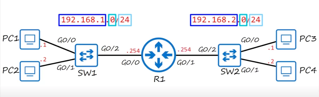
Consider the following network diagram. We have two networks, two LANs, connected via a router, R1. The router is placed between two switches, SW1 and SW2. SW1, PC1, and PC2 are on the 192.168.1.0/24 network, and SW2, PC3 and PC4 are on the 192.168.2.0/24 network.
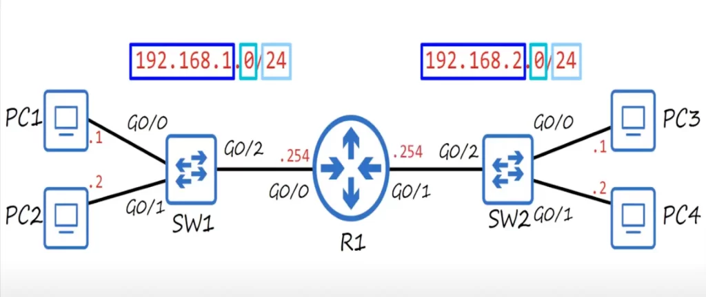
*All PCs in a network have IP addresses in the same Layer 3 network, e.g., in the network 192.168.1.0/24, PC1’s IP address is 192.168.1.1, and PC2’s IP address is 192.168.1.2. In the network 192.168.2.0/24, PC3’s IP address is 192.168.2.1 and PC4’s is 192.168.2.2.
In these network IP addresses, the first three octets, 192.168.1 and 192.168.2, represent the network itself, and only the last octet (0) changes to represent the end hosts on the network, the PCs.
Note that the router needs an IP address for each network it is connected to. So R1’s G0/0 interface is given an IP address of 192.168.1.254 and its G0/1 interface is given an IP address of 192.168.2.254.
The /24 notation tells the router what part of the IP address represents the network and what part represents the end hosts, the PCs. /24 means that the first 3 octets represent the network.
If PC1 sends a frame to the broadcast MAC address of all Fs, SW1 will receive the frame, and it will forward it out of all interfaces except the interface the frame was received on. So SW1 sends the frame out of G0/1 and G0/2, and PC2 and R1 receive the frame. However, that’s where it ends. The broadcast is limited to the local network, it doesn’t cross the router and go to SW2, PC3, and PC4.
This was just a brief introduction to routing. We will build on this knowledge in upcoming lessons to more fully understand routing.
IPv4 header
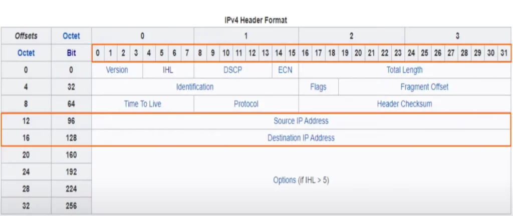
This is a chart from Wikipedia showing the IPv4 header. IP, or Internet protocol, is the primary Layer 3 protocol in use today, and version 4 is the version in use in most networks. The IPv4 header size varies between 20 and 60 bytes.
As you can see, there are a lot of different fields in the IPv4 header, more than in the Ethernet header. We are concerned with two fields, the source IP address and destination IP address. These fields are each 32-bits in length (4 bytes), as you can see they stretch from 0 to 31 in this chart.
IPv4 address structure and representation
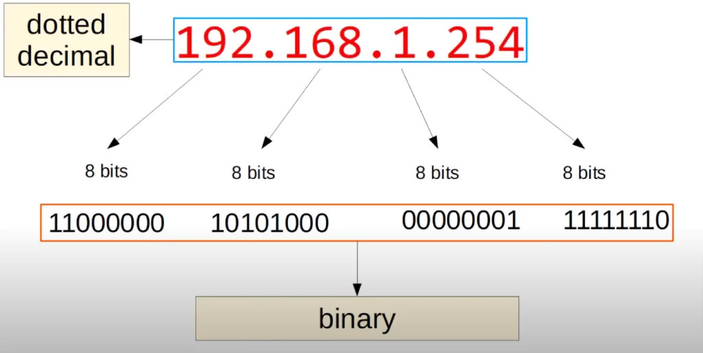
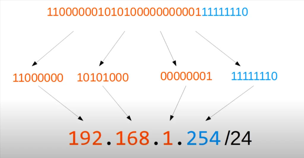
Let’s look at this IPv4 address, 192.168.1.254. An IPv4 address is 32 bits long, so each of these four groups of numbers represents 8 bits. 192 represents 8 bits, 168 represents 8 bits, 1 represents 8 bits, and 254 also represents 8 bits.

If we write these 8 bits out as 1s and 0s, 192 is 11000000, 168 is 10101000, 1 is 00000001, and 254 is 11111110. This way of writing numbers using just 0s and 1s is called binary. However, binary is difficult to read and understand for humans, so IP addresses are written using dotted decimal.
Understanding binary is important for understanding IPv4 addresses, so shortly we will practice converting IPv4 addresses between binary and dotted decimal.
But first, let’s review decimal and hexadecimal.
You may find it helpful to review this post on number system conversions: CCNA 200-301 Math study notes
Decimal and hexadecimal review
In decimal, also known as base 10, each digit increases by a factor of 10 (i.e., 1, 10, 100, 1000, 10,000, etc.).
For example, the number 3294 consists of 3 units of 1000, 2 units of 100, 9 units of 10, and 4 units of 1.
3×1000 + 2×100 + 9×10 + 4×1 = 3294.
| 107 | 106 | 105 | 104 | 103 | 102 | 101 | 100 |
| 1000000 | 100000 | 10000 | 1000 | 100 | 10 | 1 | |
| 3 | 2 | 9 | 4 |
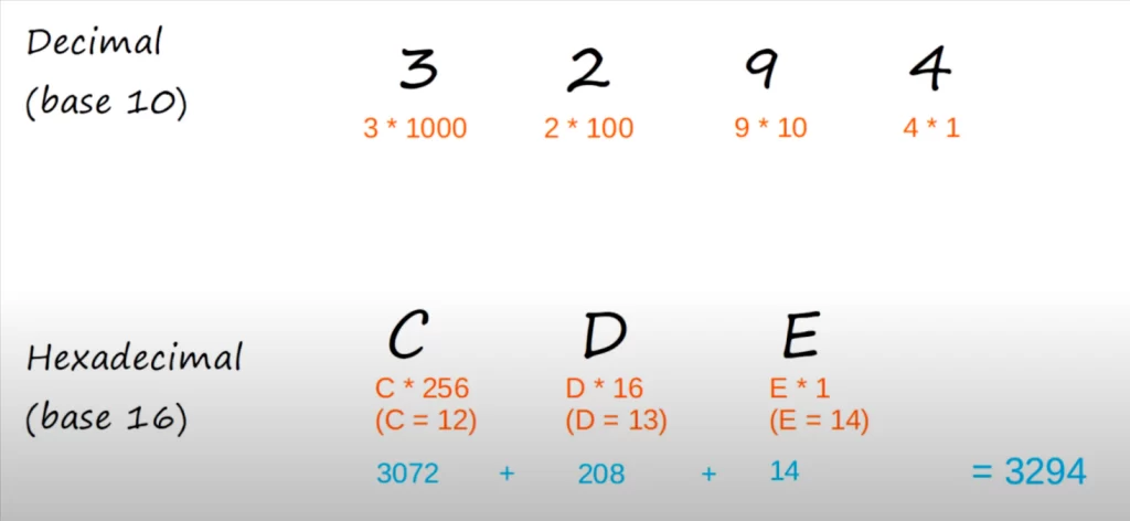
Now, let’s look at this number in hexadecimal. The decimal number 3294 is written in hexadecimal as CDE. But how come?
In hexadecimal, each digit increases by a factor of 16 (i.e., 1, 16, 256, 4096, etc.).
The value of the first digit is E x 1. Since E = 14 in decimal, the value of the first digit in decimal = 14.
The value of the second digit is D x 16. Since D = 13, so this value is 208.
The value of the third digit is C x 256. Since C = 12, so this value is 3072.
CDE = 12×256 + 13×16 + 14×1 = 3072 + 208 + 14 = 3294.
| 167 | 166 | 165 | 164 | 163 | 162 | 161 | 160 |
| 4096 | 256 | 16 | 1 | ||||
| C (12) | D (13) | E (14) |
Binary number system
Now let’s look at binary and converting binary octets to decimals.
Looking back at this IP address 192.168.1.254, let’s look at how each of these numbers is written in binary, starting with 192, which is 11000000.
Binary is base 2, meaning each digit increases by a factor of 2 (i.e., 1, 2, 4, 8, 16, 32, 64, 128, etc.).
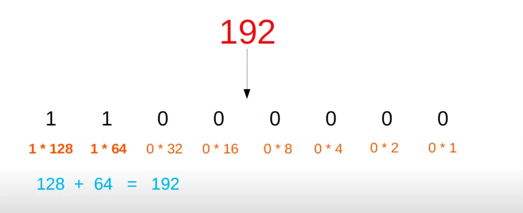
>First, let’s understand why 192 equals 11000000 in binary.
| 27 | 26 | 25 | 24 | 23 | 22 | 21 | 20 |
| 128 | 64 | 32 | 16 | 8 | 4 | 2 | 1 |
| 1 | 1 | 0 | 0 | 0 | 0 | 0 | 0 |
11000000 means,
1×128 + 1×64 + 0x32 +0x16 + 0x8 +0x4 + 0x2 +0x1 = 192.
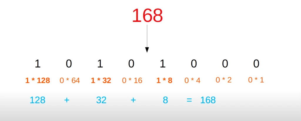
>Next let’s look at how 168 is converted to binary, which is 10101000.
10101000 means,
1 unit of 128, 0 unit of 64, 1 unit of 32, 0 unit of 16, 1 unit of 8, 0 unit of 4, 0 unit of 2, and 0 unit of 1.
>Next up is 1, which is the decimal representation of binary 00000001. This is pretty simple. 1 is equal to 1 unit of 1.
>Finally, let’s see why 11111110 in binary = 254 in decimal.
Binary 11111110 represents 1 unit of 128, 1 unit of 64, 1 unit of 32, 1 unit of 16, 1 unit of 8, 1 unit of 4, 1 unit of 2, and 0 unit of 1. Add all those together, and you get 254.
The range of possible numbers that can be represented with 8 binary bits ranges from 0, if all bits are 0, to 255, if all bits are 1 (because 128 + 64 + 32 + 16 + 8 + 4 + 2 + 1 equals 255).
Binary to decimal conversion practice
You can find more practice examples of converting binary to decimal notation starting from 13:06 and through to 15:06 in Jeremy’s IPv4 Addressing (Part 1) video, cited below under Key references.
Decimal to binary conversion practice
Example 1: convert 221 to binary.
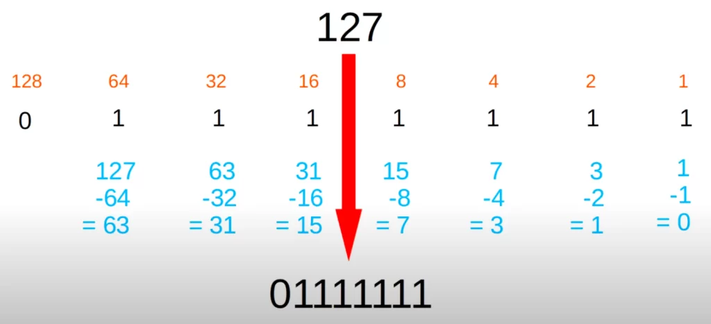
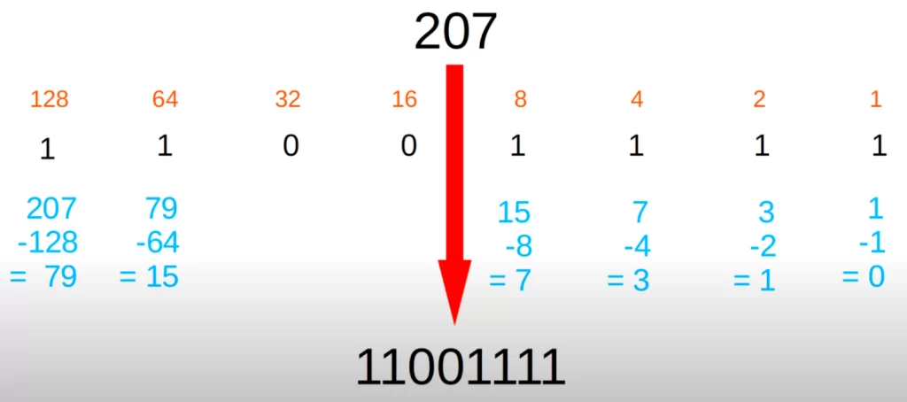
First, write out the value of each bit in a binary octet (128, 64, 32, etc.) like in the table below. Then starting from the left (128) try to subtract each number (the value of each bit) from the decimal number you’re trying to convert. If you can subtract, write 1 under the bit value. If you cannot subtract, write zero.
| 27 | 26 | 25 | 24 | 23 | 22 | 21 | 20 |
| 128 | 64 | 32 | 16 | 8 | 4 | 2 | 1 |
| 221-128= 93 | 93-64= 29 | You cannot | 29-16= 13 | 13-8= 5 | 5-4= 1 | You cannot | 1-1= 0 |
| 1 | 1 | 0 | 1 | 1 | 1 | 0 | 1 |
Therefore, 221 equals 11011101.
Example 2: convert 127 to binary.
Example 3: convert 207 to binary.
IPv4 addresses (network portion, host portion)
An IPv4 address is a series of 32 bits comprising 4 octets and written in dotted decimal format.
The /24 is used to identify which part of the IP address represents the network and which part represents the end host. /24 means the first 24 bits (the first 3 octets) of an IP address represent the network portion of the address, and the remaining 8 bits represent the end host. So 192.168.1 is the network portion of the address, and 254 is the host portion.
If you want some more binary to decimal conversion practice, try to convert these 32 binary bits into an IPv4 address. The 32 bits can be split into 4 octets, then the four octets can be converted into dotted decimal, like this:
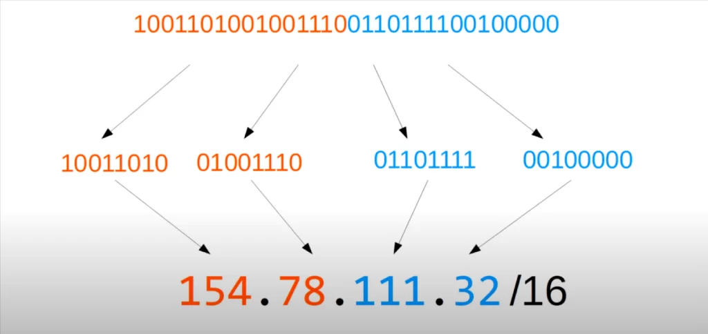
This time /16 is used instead of /24. So the first 16 bits (the first 2 octets) represent the network portion of the IP address, and the last two octets are the host portion. Therefore, 154.78 is the network portion, and 111.32 is the host portion.
Here’s another IPv4 address. Try to convert these 32 bits into dotted decimal. You can divide the 32 bits into 4 octets, and then convert the octets into dotted decimal, like this:
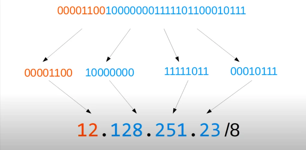
This time the prefix is /8, meaning the first 8 bits represent the network portion, and the last three octets are the host portion. So, 12 is the network portion, and 128.251.23 is the host portion.
IPv4 address classes
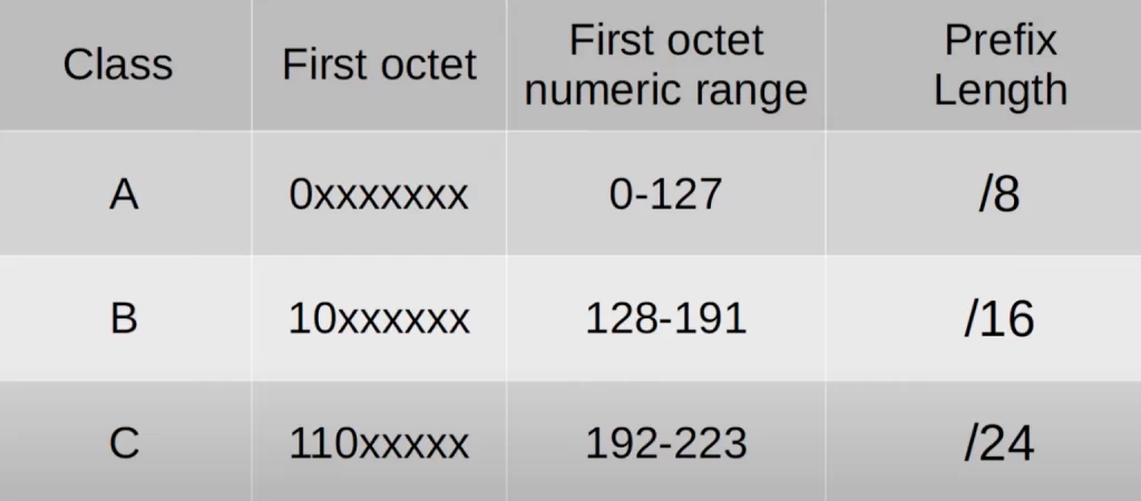
IPv4 addresses are split up into 5 different classes. The class of an IPv4 address is determined by the first octet of the address. The first class is Class A, which has a first octet beginning with 0. If the first octet begins with 0, that means that the numeric range of the first octet is from 0 to 127, because 64 + 32 + 16 + 8 + 4 + 2 + 1 = 127.
| Class | First octet | First octet numeric range |
| A | 0XXXXXXX | 0-127 |
| B | 10XXXXXX | 128-191 |
| C | 110XXXXX | 192-223 |
| D | 1110XXXX | 224-239 |
| E | 1111XXXX | 240-255 |
The second class is Class B, which has a first octet beginning with 10, and therefore a numeric range of 128 to 191. The third class is Class C, which has a first octet beginning with 110, and therefore the numeric range for the first octet is 192 to 223. Class D has a first octet beginning with 1110, and the numeric range of the first octet is 224 to 239. Finally, Class E has a first octet beginning with 1111, and therefore the numeric range for the first octet is 240 to 255.
The classes of address we will focus on are A, B, and C. Addresses in Class D are reserved for multicast addresses (e.g., OSPF routers use 224.0.0.5 and 224.0.0.6 to address messages to other OSPF routers). Class E addresses are reserved for experimental uses.
Loopback addresses
*The end of the Class A range is usually considered to be 126, not 127. The 127 range is reserved for loopback addresses, so it’s generally not considered part of the Class A range. The loopback address range is anything with a first octet of 127, so 127.0.0.0 to 127.255.255.255.
Note: the 0 range in Class A is also reserved (for documentation and examples), so some might say Class A really begins at 1, making the range 1-126. Practically speaking, the usable range is 1-126.
*Loopback addresses are used to test the network stack (OSI and/or TCP/IP) of the local device. If a device (e.g., a PC) sends any network traffic to an address in this range, it is simply processed back up the TCP/IP stack as if it were traffic received from another device.
In the image on the left, we used a Windows PC to ping 127.0.0.1, and you can see the responses. The PC is responding to its own pings.
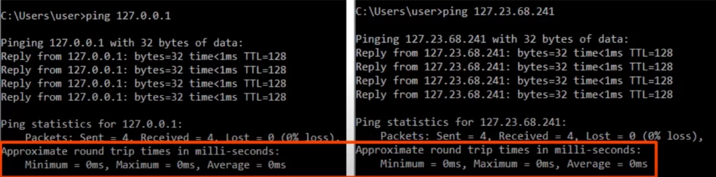
In the image on the right, a ping was sent to a random IP address in the 127 range, 127.23.68.241, and again we see the PC responding back to its own ping.
Notice the round trip times, all 0 milliseconds. That’s because the traffic isn’t going anywhere. The PC is just sending and receiving these pings to and from itself.
IPv4 address classes cont’d
Here’s the earlier chart of IPv4 classes slightly modified. The chart only shows classes A, B, and C. A prefix length column is added, indicating the length of the network portion of the address.
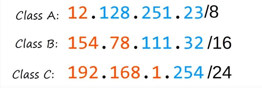
Class A addresses use a /8 prefix, Class B addresses use a /16 prefix, and Class C addresses use a /24 prefix.
If we look again at these three addresses we used in our examples, we can see they are Class A, Class B, and Class C addresses, and their prefix lengths match the table.
In Class A, there are fewer possible network addresses, however because the host portion is very long, there can be many hosts on each network. Class C is the opposite, there are many more possible networks, but because the host portion is smaller there are fewer hosts on each network.
Let’s look at the numbers. This is another chart taken off of wikipedia.
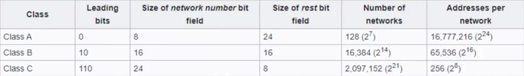
>The leading bits column refers to the first bits of the first octet, displayed in the previous table.
>The “size of network number bit field” displays the number of bits in the network portion of the IP address, 8 for Class A, 16 for Class B, and 24 for Class C.
>The “size of rest bit field” indicates the remaining number of bits in the address, which is the host portion of the address. 24 bits for Class A, 16 for Class B, and 8 for Class C.
>The “number of networks” column displays the number of possible networks in each class. Class A has 128 possible networks, Class B has about 16,000 networks, and Class C has about 2 million networks.
How were these numbers calculated? Let’s start with Class A. The network portion is one octet, the first octet, but the first bit in the first octet is reserved to indicate that it is a Class A address. This leaves 7 bits usable for networks or 2^7 = 128. In a Class B network, the first two bits are reserved to indicate that it is a Class B address, leaving 14 bits (16 – 2) for networks, so 2^14. In a Class C network, the first three bits are reserved to indicate the class, leaving 24 – 3 = 21.
>“Addresses per network” is the maximum number of addresses, including the network address and broadcast address. Class A allows about 16.7 million hosts in each network, Class B allows about 65,000 hosts in each network, and Class C allows 256 hosts in each network.
Notice how the number of addresses per network for each class is calculated: 2 to the power of 8, 16, or 24, the exponents being the length of the host portion.
Note: the first address in each network is the network address and it cannot be assigned to hosts. The last address of the network is the broadcast address, which is the Layer 3 address used when you want to send traffic to all hosts in the local network, and it too cannot be assigned to hosts, so really the host count is two less, for example, 254 in Class C.
Netmasks
A network mask (netmask) is a 32-bit number that is used to identify the network portion of an IP address. It is used in conjunction with an IP address to determine which hosts are in the same network and which hosts are in different networks.
A netmask is created by setting network bits to 1s and host bits to 0s. In this way, the subnet mask separates the IP address into the network and host portions. For example, the IP address 192.168.1.100 has a network mask of 255.255.255.0. This means that the first 24 bits of the IP address (192.168.1) are used to identify the network, and the last 8 bits (100) are used to identify the host.
The prefix length of an IP address indicates the size of the network portion of the address. The prefix length is often written in CIDR notation, which is a shorthand notation for representing IP addresses and their subnet masks. In CIDR notation, the prefix length is written after the IP address, separated by a slash.
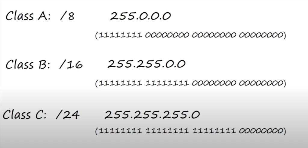
The subnet mask value can be expressed using either the dotted decimal notation or the CIDR notation. For example, the subnet mask of a Class A IPv4 address in dotted decimal is 255.0.0.0. That’s the dotted decimal version of 11111111, followed by 24 zeros. In CIDR notation, often called prefix length, a slash 24 (“/24”) is used to indicate the same subnet mask value of 255.0.0.0.
Using a slash followed by the length of the prefix is a newer way of indicating the subnet mask. On Juniper network devices you use the slash notation. However, Cisco devices use an older way of indicating the length of the subnet mask, i.e., using a dotted decimal netmask.
These prefix lengths and netmasks are the same things, just written in different ways.
Network address
If the host portion of an IP address is all 0’s, it means it is the network address, the identifier of the network itself (network identifier or network ID). In our diagram here, the network on the left has the IP address 192.168.1.0/24.
We know that /24 means the first three octets are the network portion, and the last octet is the host portion. Since, the host portion is 0, it means the last octet, the host portion, is all 0s. Therefore, this address, 192.168.1.0/24, is the network address. The network address cannot be assigned to a host.
The network address is the first address of the network, but the first usable address is one above the network address, in this case it’s 192.168.1.1, which is assigned to PC1.
Broadcast address
The broadcast address of the network is the last address of the network. Like the network address, the broadcast address cannot be assigned to a host. So although it’s the last address in the network the last usable address is 1 under the broadcast address, in this case, that’s 192.168.1.254, the address assigned to R1’s G0/0 interface.
So the broadcast address is the Layer 3 address used to send a packet to all hosts on the local network. If a packet is sent with the destination IP address 192.168.1.255, what do you think will be the destination MAC address of the frame it is encapsulated in?
It will be all F’s, the broadcast MAC Address. If PC1, for example, sent a ping to 192.168.1.255, it would be received by PC2 and R1’s G0/0 interface.
Key learnings
*Dotted decimal and binary conversion. Binary is how computers think, but 32 bit IPv4 addresses are difficult for humans to understand, so we convert IPv4 addresses to dotted decimal form to make them easier to read and remember.
*IPv4 addresses consist of a network portion and a host portion. Hosts on the same network will have the same network portion, but a unique host portion of their IP addresses.
*IPv4 address classes, and the characteristics of classes A, B, and C.
*Prefix lengths/netmasks. We looked at the different ways of indicating the length of the network prefix, by writing the prefix length with a slash or by using a netmask.
*Network and broadcast addresses. The network address has a host portion of all 0s, and is used to identify the network itself. The broadcast address has a host portion of all 1s, and is used to send network traffic to all hosts on the network.
Practice quiz questions
Quiz question 1
Convert the following IPv4 address to dotted decimal notation:
00111111 00111000 11100111 00010011
The answer is 63.56.231.19.
You can find nine more practice questions for this lesson in Jeremy’s IPv4 Addressing (Part 1) video, cited below.
You may also want to check out Quiz question 1 in the lesson IPv4 address configuration and verification.
Key references
Note: The resources cited below (in the “Key references” section of this document) are the main source of knowledge for these study notes/this lesson, unless stated otherwise.
Free CCNA | IPv4 Addressing (Part 1) | Day 7 | CCNA 200-301 Complete Course
Related content
Classless IPv4 addressing and subnetting
Compliance frameworks and industry standards
How data flow through the Internet
How to break into information security
IT career paths – everything you need to know
Job roles in IT and cybersecurity
Network security risk mitigation best practices
The GRC approach to managing cybersecurity
The penetration testing process
The Security Operations Center (SOC) career path
Back to DTI Courses


