This is Part 2 of 2 of Ethernet LAN switching CCNA study notes. Part 1, How traffic flows within a LAN, gave a high-level overview of how switches move frames within a LAN using MAC addresses. This lesson looks at how PCs within a LAN communicate and how switches forward frames to their destination. We look at how switches use MAC addresses to direct network traffic through the switch to the appropriate outbound port toward the destination. We study how a MAC address table is populated and how the Address Resolution Protocol (ARP) is used to resolve an IP address to a MAC address. This post constitutes Issue 3 of my CCNA 200-301 study notes.
- ARP – Address Resolution Protocol
- ARP request
- ARP reply
- ARP table
- GNS3
- ping – how it works/introduction
- Wireshark packet capture
- MAC address table
- Clearing the MAC address table
- Ethernet frame review
- Command review
- Key learnings
- Practice quiz questions
- Key references
You may also be interested in CCNA 200-301 study notes.
ARP – Address Resolution Protocol
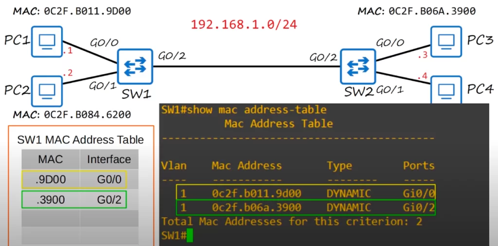
Below is a small network. The switch interfaces are GigabitEthernet, hence the G0/0, G0/1, and G0/2 on each switch.
Note that the OUI, the first half of the MAC address that identifies the maker of the device, is the same for each PC, 0C2F.B0, so the PCs were all made by the same company. The second half of each device’s MAC address is unique, since that represents the device itself. Sometimes we may just use the last four digits of a MAC address to refer to a MAC address, to keep things simple.
And we may reference only the last digit of an IP address, to keep things simple. The network IP address is 192.168.1.0/24. Then .1 represents PC1’s IP address. PC1’s real IP address is 192.168.1.1. PC2’s IP address is 192.168.1.2, PC3’s IP address is 192.168.1.3, and PC4’s IP address is 192.168.1.4.
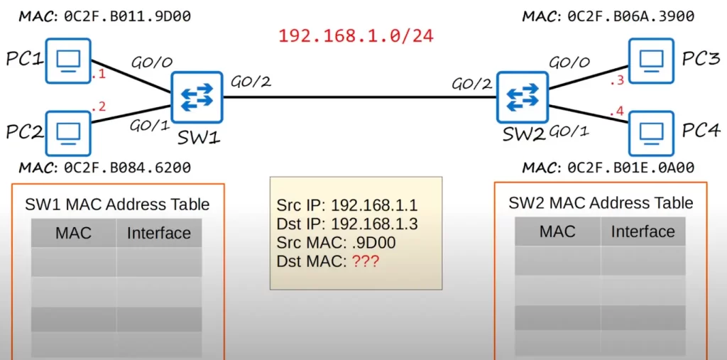
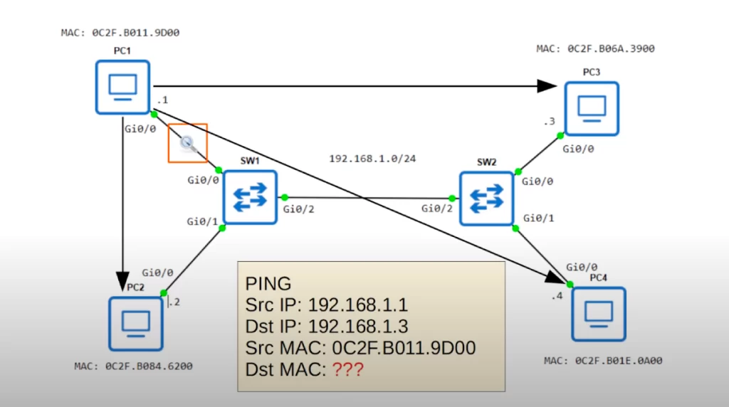
PC1 wants to send some data to PC3. The source IP is 192.168.1.1 and the destination IP is 192.168.1.3. The source MAC is 0C2F.B011.9D00. However, PC1 does not know PC3’s MAC address. PC1 has to discover PC3’s MAC address first.
PC1 needs PC3’s MAC address to create a L2 header which will deliver the frame to the next hop device (PC3 in our example). PC1 uses ARP, the Address Resolution Protocol, to learn PC3’s MAC address.
Remember, switches are Layer 2 devices, they do not operate at Layer 3, so switches need to use MAC addresses, not IP addresses.
ARP It is used to discover the Layer 2 address, the MAC address, of a known Layer 3 address, the IP address. In our example PC1 knows PC3’s Layer 3 address, 192.168.1.3, but it does not know PC3’s Layer 2 address (PC3’s MAC address) yet.
The ARP process consists of two messages: the ARP request, sent by the device that wants to know the MAC address of the other device, and the ARP reply, which is sent to inform the requesting device of the MAC address. In our example, PC1 would send the ARP request, and PC3 would send the ARP reply.
The ARP request is sent as a broadcast Ethernet frame. Broadcast means it is sent to all hosts on the network. Because the Layer 2 address of the destination host is unknown, a host (PC1 in our example) broadcasts the request and waits for a reply from the correct device.
The ARP reply is unicast. A unicast frame is sent to only one host, in this case it’s sent to the host that sent the ARP request.
Let’s look at how ARP works in our sample network.
ARP request
At the bottom in the following diagram (the yellow box) is the frame that PC1 wants to send to PC3. But first PC1 has to send an ARP request frame (the blue box). The point of an ARP request is that PC1 learns the MAC address of PC3 so that PC1 can construct a L2 header to deliver the frame to PC3.
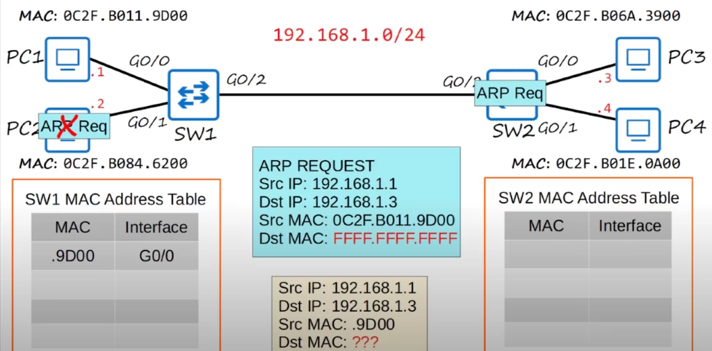
The source and destination IP addresses, as well as the source MAC address, are the same for both the ARP request message as well as for the frame PC1 wants to send to PC3. However, look at the destination MAC address. FFFF.FFFF.FFFF is the broadcast MAC address. This is the destination MAC address used when a device wants to send Ethernet frames to all other devices on the local network.
So PC1 prepares the ARP request and sends it out of its network interface, and it is received by SW1. SW1 then adds PC1’s MAC address to its MAC address table. When a MAC address is learned in this way is it called a dynamic MAC address.
Since the destination MAC address is all Fs, SW1 broadcasts the frame out of all of its interfaces except the interface it was received on. This is very much like what a switch does with an unknown unicast frame. When a switch receives a unicast frame with a destination MAC address that it does not know, it floods the frame out of all ports in the same VLAN as the received frame, except for the port on which the frame was received. This is called unknown unicast flooding.
SW1 sends the frame out of G0/1 and G0/2, but not G0/0 because it received the frame on that interface. PC2 receives the frame, but it ignores it because the destination IP address does not match PC2’s IP address.
Then SW2 learns PC1’s MAC address and adds it to its MAC address table, associating it with its G0/2 interface since that’s the interface SW2 received the frame on.
Since the destination MAC address is the broadcast MAC address, SW2 also sends the frame out of all interfaces, except the one the frame was received on. That means SW2 sends the frame out of G0/0 and G0/1. PC4 ignores the frame because the destination IP address does not match its own. However, PC3 accepts the frame and processes it. PC3 will now send an ARP reply.
ARP reply
Below, you can see the ARP reply frame (the blue box). The source IP is PC3’s IP, and the destination IP is PC1’s IP. The Source MAC is PC3’s MAC address, and the destination is PC1’s. Although the ARP Request message was a broadcast message, because PC1’s MAC address was used as the source MAC address of the ARP request message, PC3 now knows PC1’s MAC address so it can send the ARP reply directly to PC1, without having to broadcast the frame.
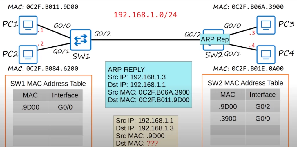
PC3 sends the frame out of its network interface, and it is received by SW2. SW2 learns PC3’s MAC address and enters it into its MAC address table, associating it with the G0/0 interface.
Since this is a known unicast frame and SW2 already has an entry for the destination MAC address in its MAC address table, SW2 will simply forward the frame out of the proper interface in the MAC address table, it will not flood it like an unknown unicast frame or a broadcast frame. Because SW2 learned PC1’s MAC address on the G0/2 interface, it will send the frame out of that interface toward SW1. SW1 receives the frame, and since it has already learned PC1’s MAC address on the G0/0 interface, SW1 forwards the frame out of the interface, and PC1 finally receives the ARP reply. PC1 will then use that information to add an entry for PC3 to its ARP table, which is used to store IP address to MAC address associations.
ARP table
This is a screenshot of part of an ARP table from a PC. You can use the arp -a command to view the ARP table from a PC.
The Internet address column displays IP addresses. The Physical address column displays the MAC addresses that correspond to the IP addresses. If the Type column displays static, it means that it is a default entry, it was not learned by sending an ARP request. If the Type column displays dynamic, that means that the entry was learned by sending an ARP request and receiving an ARP reply.
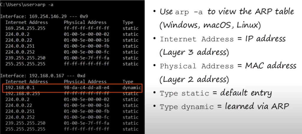
Note, for example, the entry with an IP address of 192.168.0.1 and its MAC address next to it: the PC used ARP to learn that MAC address, which belongs to a home router in this example.
GNS3
GNS3, a network emulator software, was used to recreate the above network topology. GNS3 is similar to Packet Tracer in that it allows you to create networks and practice configurations on Cisco devices, but it is also different in some key ways. Packet Tracer is a network simulator, designed to simulate the operation of a real network. GNS3, however, runs actual Cisco IOS software, so these are real Cisco switches running virtually. However, GNS3 requires you to purchase your own copies of Cisco IOS, so although GNS3 itself is free, using Cisco IOS with GNS3 is not. You can get GNS3 at gns3.com.
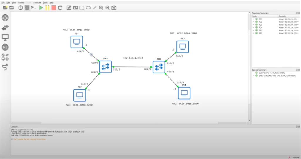
Below is our topology. Notice the magnifying glass. This is a feature of GNS3 that integrates with Wireshark. We will use it to analyze what traffic passes between PC1 and SW1.
We are going to send a ping from PC1 to PC3.
Just like our previous example, PC1 does not know the destination MAC address of PC3, so PC1 has to send an ARP request.
PC3 responds to the ARP request since its IP address matches the destination IP address in the ARP request.
PC1 then learns the MAC address of PC3, adds it to its ARP table, and uses that information to add the destination MAC address to the ping it wants to send.
ping – how it works/introduction
Ping is a network utility that is used to test reachability, for example, to test if two computers can reach each other.
Ping measures the round-trip time, for example the time from PC1 to PC3, then back to PC1. The ping command measures the round-trip time for an ICMP echo request and reply – the time it takes for the echo request to be sent, received, and replied to.
Ping uses two messages: ICMP Echo request, and ICMP echo reply. This is similar to an ARP request and ARP reply. However, the PC will not broadcast the ICMP echo request, it is sent to a specific host. So the PC has to know the MAC address of the destination host, which is why ARP must be used first.
The command to use ping is: ping, followed by the IP address you want to ping to, for example, ping 192.168.1.3, to ping PC3 in our network.
Let’s look at the ping process.
This is the Cisco IOS CLI output for PC1. Cisco routers are used to simulate PCs, since it’s easier than setting up virtual PCs to ping in GNS3.
The command ping 192.168.1.3 is used to send an ICMP echo request to PC3.
Note the message, “Sending 5, 100-byte ICMP echos to 192.168.1.3.”
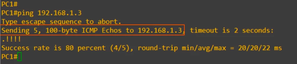
By default, a ping in Cisco IOS sends 5 ICMP echo requests, and then you should get 5 ICMP echo replies back. The default size of each ping is 100 bytes.
In the line under “Sending 5, 100-byte ICMP echos to 192.168.1.3”, the period indicates a failed ping, and the exclamation points indicate a successful ping.
Note the result, success rate is 80 percent, 4 out of 5.
Also note the round trip time, showing the minimum, average, and maximum time of the 4 successful pings.
The first ping failed because of ARP. PC1 did not know the destination MAC address, so it had to use ARP, and at that time the first ping failed. After PC1 learned PC3’s MAC address, the subsequent pings succeeded.
Let’s look at the ARP table here. The command for Windows, MacOS, and Linux was arp -a. In Cisco IOS it is show arp, from privileged EXEC mode.
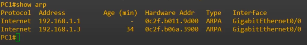
Notice there is an entry for 192.168.1.1, which is PC1 itself, and then below it 192.168.1.3, which is PC3.
Age refers to the time elapsed since the ARP entry was last learned or updated.
The interfaces listed refer to the physical or logical network interfaces through which the device (PC1) learned the IP-to-MAC address mappings.
The Interface column indicates on which physical interface the router should send the packet out to reach the destination. The interfaces listed are from the perspective of the router, indicating the outgoing interface on which the learned MAC address can be reached.
Wireshark packet capture
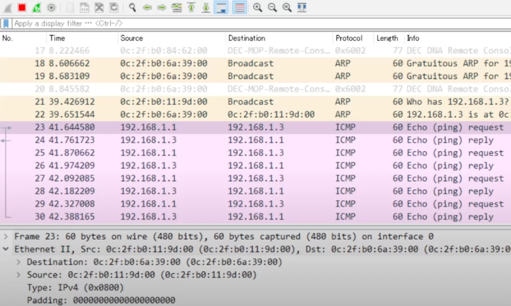
Below is a screenshot from Wireshark. Wireshark allows you to perform packet captures to analyze the contents of network traffic.
Notice the Protocol column. ARP, followed by ICMP, which is ping.
Here’s the first ARP packet. The source MAC is 0c:2f:b0:11:9d:00, which is PC1’s MAC. The destination is broadcast, which is all Fs. Look at the info at the end: “Who has 192.168.1.3? Tell 192.168.1.1”. This describes the purpose of ARP. The ARP request is asking which MAC address has an IP address of 192.168.1.3, and to send the reply to itself, 192.168.1.1.
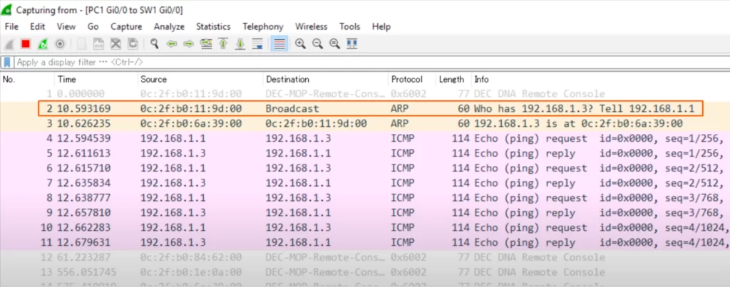
Next is the ARP reply. The source address is 0c:2f:b0:6a:39:00, PC3’s MAC, and the destination is PC1’s MAC. Look at the info section again: “192.168.1.3 is at 0c:2f:b0:6a:39:00”. PC3 is telling PC1 its MAC address. After that there are 4 ICMP echo requests, and 4 ICMP echo replies. Note that the ICMP echo requests have a source IP of PC1 and destination of PC3, and the ICMP echo replies have a source of PC3 and destination of PC1.
MAC address table
Let’s look at the MAC address table on a Cisco switch. The command to view it is, show mac address-table. Old versions of Cisco IOS use show mac hyphen address hyphen table, but newer versions got rid of the first hyphen.
Let’s look at the sections of the MAC address table.
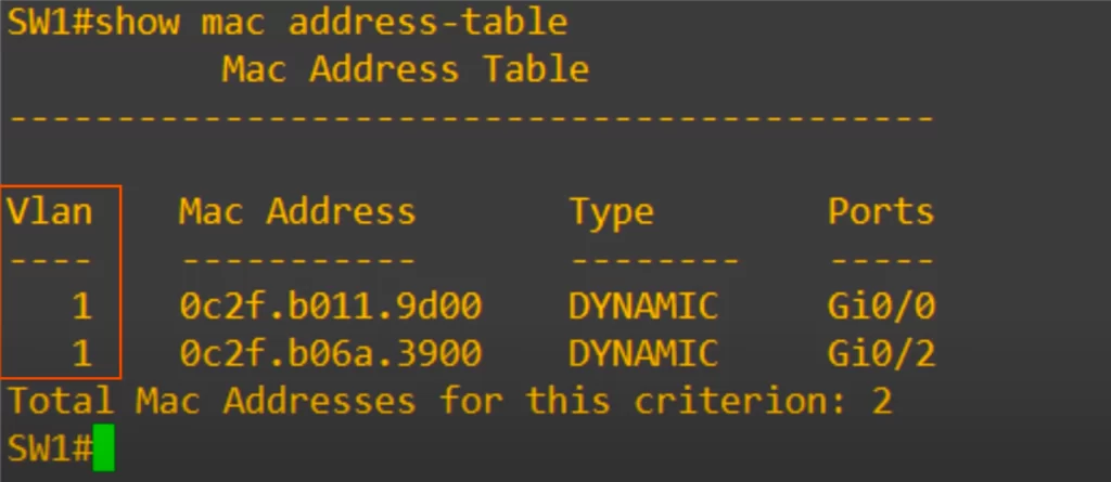
First is the VLAN. As displayed, the default is 1.
Next is the MAC address column, you can see PC1 up top and PC3 on the bottom.
Next is the type. Both of these MAC addresses were learned dynamically, they were not manually configured on the switch.
Finally, Ports, which is another word for interface.
You can see that this matches the small MAC address table in our earlier diagram.
Clearing the MAC address table
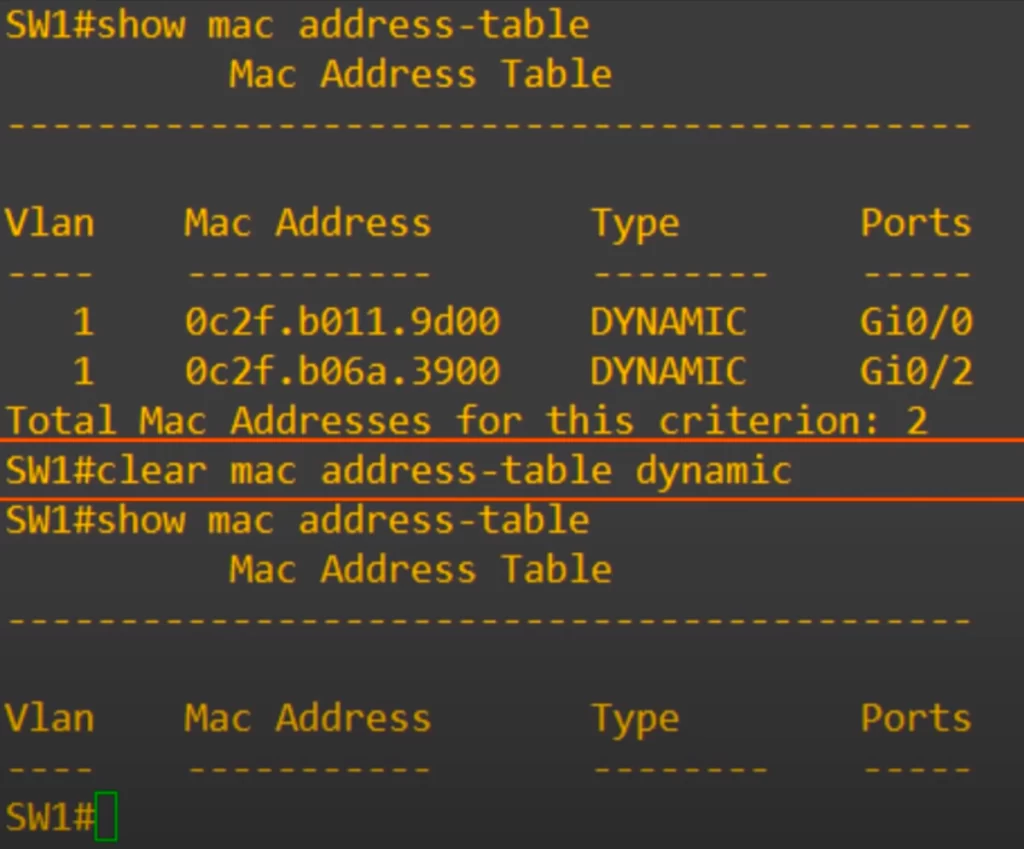
Dynamic MAC addresses are removed from the MAC address table after 5 minutes. This is known as aging. If the switch does not get any traffic from that MAC address for 5 minutes, it will remove the entry from the MAC address table. However, you can also manually remove MAC addresses from the table.
Here the show mac address-table command was used and you can see the entries for PC1 and PC3. Then the command clear mac address-table dynamic was used. The command cleared all the dynamic MAC addresses.
You can add some additional options to the command if you do not want to clear all the MAC addresses from the table.
Again we used show mac address-table, and you can see both entries, for PC1 and PC3. But this time we used a different command to clear a specific entry, i.e., we used clear mac address-table dynamic address, followed by the mac address.
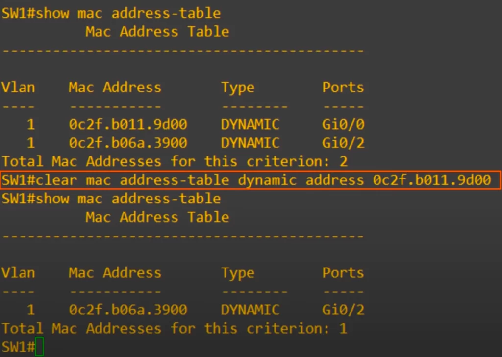
We applied the command clear mac address-table dynamic address, followed by PC1’s MAC address. Then when we used show mac address-table again, only PC3’s MAC address can be seen.
Let’s learn one more option to clear the MAC address table.
Again, show mac address-table shows both PC1 and PC3’s MAC addresses. This time we use the command clear mac address-table dynamic interface, and then the interface.
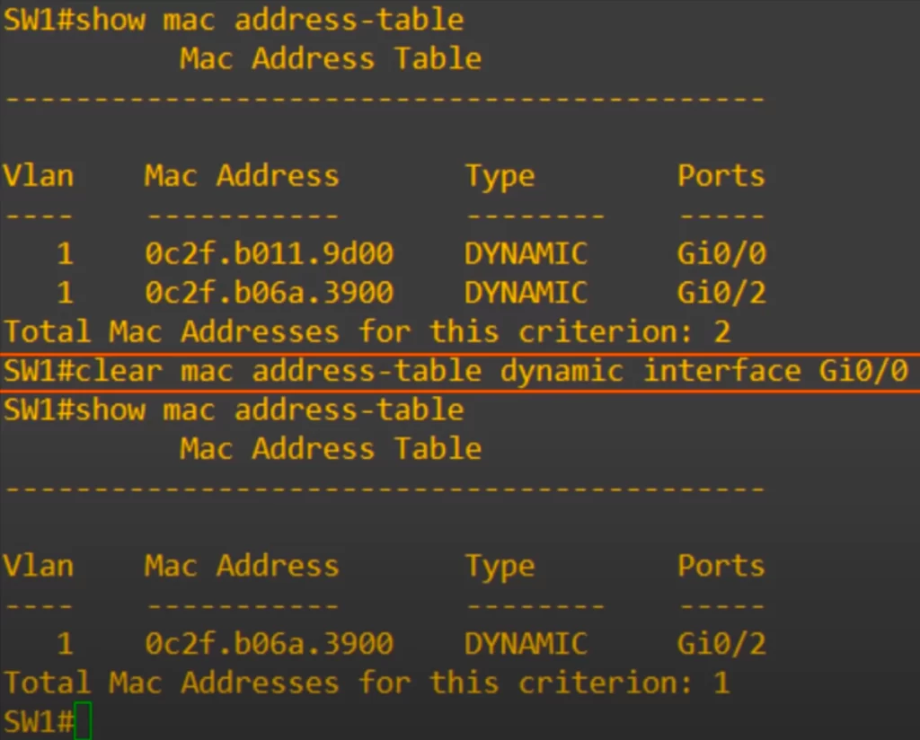
We applied the command clear mac address-table dynamic interface gi0/0. This clears all MAC address table entries for a specific interface. As you can see, once again PC1’s MAC address is removed, because it is connected to the G0/0 interface.
Ethernet frame review
In this Wireshark packet capture PC1 sent a 36-byte ping with the command: PC1#ping 192.168.1.3 size 36.
First, notice the Ethernet Type field. As noted in Part 1 of Ethernet LAN switching, How traffic flows within a LAN, IPv4’s Ethernet Type is 0x0800. The 0x just means that it’s using hexadecimal, so really it’s 0800.
Next, look at the padding. Remember, the minimum payload size for an Ethernet frame is 46 bytes, and we sent 36 byte pings, so there should be 10 bytes of padding. These zeroes are hexadecimal zeroes. Each hexadecimal digit is 4 bits, so 2 digits equals 8 bits or 1 byte. If you count the zeroes, there are 20 zeroes, so that means 10 bytes of padding.
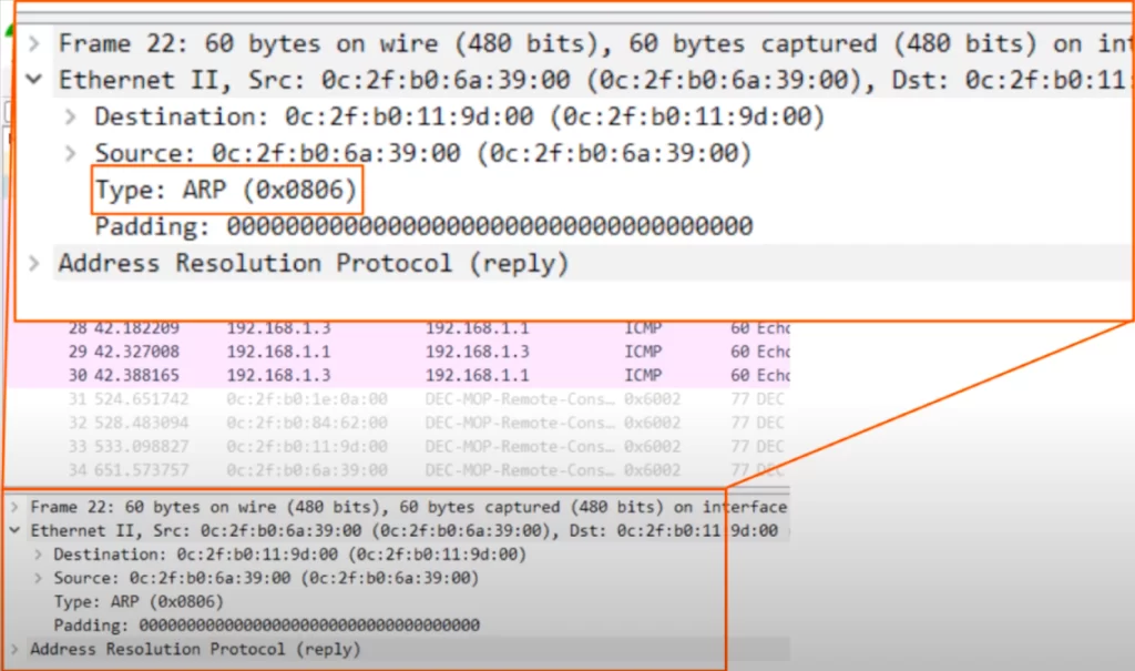
One last thing in Wireshark. This time looking at ARP. Recall, the IPv4 Ethernet Type is 0800, and the IPv6 Ethernet Type is 86DD. As you can see here, the ARP Ethernet Type of 0806. This indicates that an ARP packet is inside of this Ethernet frame.
Command review
C:\Users\user>arp -a
→the command for Windows, MacOS, and Linux to view ARP table
R#show arp
→view ARP table
SW#show mac address-table
→view MAC address table (old versions of Cisco IOS use show mac-address-table)
SW#show mac address-table dynamic
→to display only the MAC addresses learned through network communication, excluding manually configured static entries
SW#clear mac address-table dynamic
→to clear the MAC address table
SW#clear mac address-table dynamic address mac-address
→to clear a specific MAC address entry
SW#clear mac address-table dynamic interface interface
→to clear all MAC address table entries for a specific interface
Key learnings
*How ARP is used to learn the MAC address of a device for which you already know the IP address.
*How to view the ARP table on a Windows device and a Cisco IOS device.
*How ping works – how ping uses two messages, ICMP echo request and ICMP echo reply, to test host reachability in a network.
*How to view the MAC address table on a Cisco switch, and several ways to clear it.
Practice quiz questions
Quiz question 1
You send a 36-byte ping to another computer and perform a packet capture to analyze the network traffic. You notice a long series of bytes of 00000000 at the end of the Ethernet payload. How can you explain these zeroes?
A. Pings are a series of zeroes
B. They are padding bytes
C. They are the Ethernet FCS
The answer is B, they are padding bytes. The ping you sent was 36 bytes, but the minimum Ethernet payload size is 46 bytes, so a series of padding bytes must be added to meet the minimum payload size.
You can find four more practice questions for this lesson in Jeremy’s Ethernet LAN Switching (Part 2) video, cited below.
Key references
Note: The resources cited below (in the “Key references” section of this document) are the main source of knowledge for these study notes/this lesson, unless stated otherwise.
Free CCNA | Ethernet LAN Switching (Part 2) | Day 6 | CCNA 200-301 Complete Course
Free CCNA | Analyzing Ethernet Switching | Day 6 Lab | CCNA 200-301 Complete Course
Related content
Compliance frameworks and industry standards
How data flow through the Internet
How to break into information security
How traffic flows within a LAN
IT career paths – everything you need to know
Job roles in IT and cybersecurity
Network security risk mitigation best practices
The GRC approach to managing cybersecurity
The penetration testing process
The Security Operations Center (SOC) career path
Back to DTI Courses


