This is Part 1 of 2 of Ethernet LAN switching CCNA study notes. The broad learning objective of parts 1 and 2 is to understand how traffic flows within a LAN. This lesson (Part 1) gives a high-level overview of how switches move frames within a LAN using MAC addresses. In this lesson we start looking at how data moves between switches and the end hosts connected to them within LANs. Part 2, How switches forward frames, looks at how switches use MAC addresses to direct network traffic through the switch to the appropriate outbound port toward the destination. Part 2 examines how a MAC address table is populated and how the Address Resolution Protocol (ARP) is used to resolve an IP address to a MAC address. This post constitutes Issue 2 of my CCNA 200-301 study notes.
- Ethernet LAN switching – introduction
- LANs (Local Area Networks)
- OSI model PDUs review
- Ethernet frame structure
- Ethernet frame types (versions)
- Let’s summarize
- Ethernet packet – preamble and SFD
- Ethernet frame – header + L3 packet + trailer
- MAC addresses
- Unicast frames
- MAC address table / dynamic MAC addresses
- Unknown unicast / flooding
- Known unicast / forwarding
- MAC learning and frame flooding / forwarding review
- Practice quiz questions
- Key references
You may also be interested in CCNA 200-301 study notes.
Ethernet LAN switching – introduction
The way that Ethernet networks communicate is governed by a set of Ethernet standards. These standards define the Physical layer, which is responsible for the transmission of data over the network, and the Data Link layer, which is responsible for error detection and correction. The most recent version of the Ethernet standard is IEEE 802.3.
*Ethernet standards related to the Physical layer of the OSI model (Layer 1) define physical characteristics of the medium used to transfer data between devices, for example, voltage levels, maximum transmission distances (like Ethernet UTP cables’ 100 meter limit), physical connectors, cable specifications, etc.
*The characteristics that Ethernet standards related to the Data Link layer of the OSI model (Layer 2) define include: frame format (structure of an Ethernet frame), MAC addressing (a method of assigning unique identifiers to devices on an Ethernet network), CSMA/CD (a method of resolving collisions between devices on an Ethernet network), and flow control (a method of preventing devices from sending too much data at once).
*Layer 2 provides node-to-node connectivity and data transfer, for example, PC to switch, or switch to router, or router to router, etc.
*Switches operate at Layer 2.
LANs (Local Area Networks)
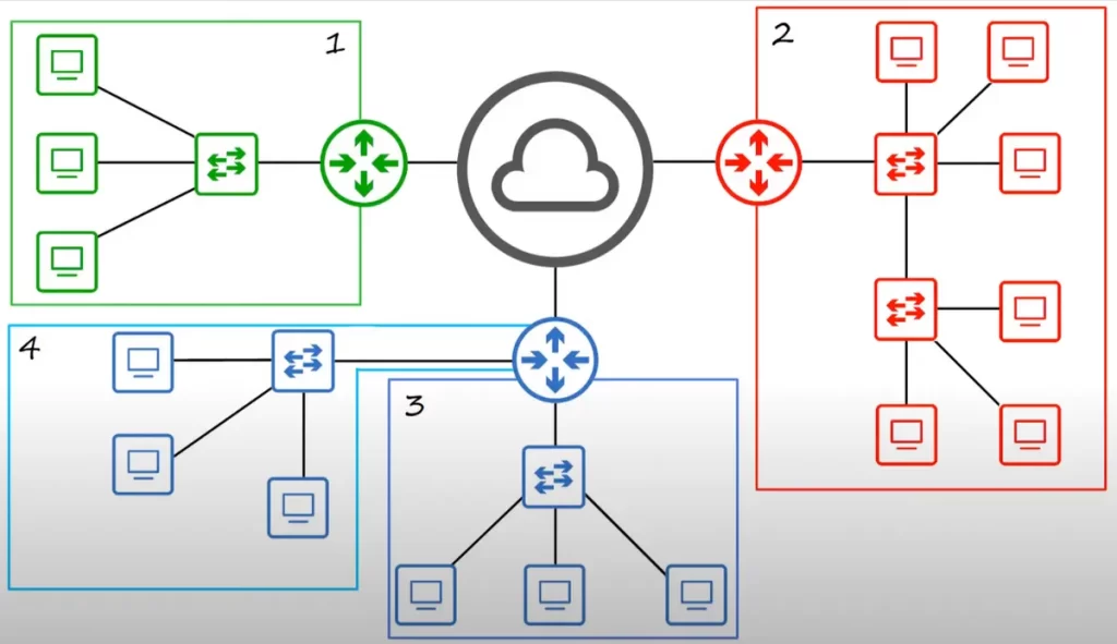
A LAN is basically a network contained within a relatively small area, such as an office floor or a home network. Routers are used to connect separate LANs. Switches do not separate LANs, but adding more switches can be used to expand an existing LAN.
Note how many LANs there are in this network topology. The green network, consisting of three PCs, one switch, and the router interface they are connected to, is one VLAN. The red network is also one LAN. Although there are two switches, it is all one LAN. Finally, we have two blue LANs. This lesson looks at how traffic is sent and received within LANs like these four LANs.
OSI model PDUs review
This diagram shows the encapsulation process as data is prepared to be sent over a network. At the top, the data prepared by the upper layers of the OSI model is simply called data.
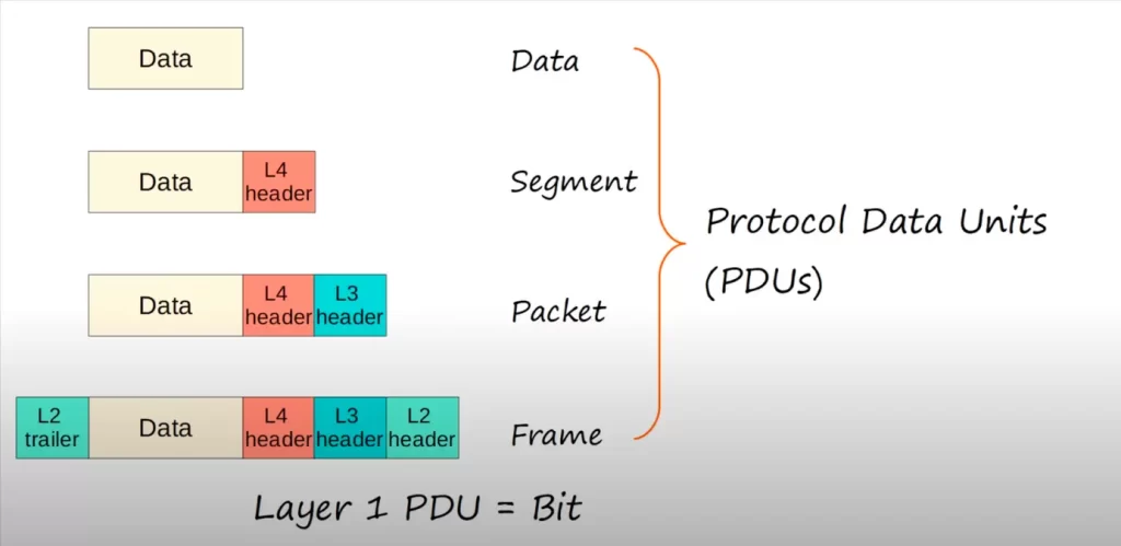
A Layer 4 header is added, and this combination of data and Layer 4 header is called a segment. A Layer 3 header is added to the segment, and it is now called a packet. Finally, a Layer 2 header and trailer are added to the packet, and it becomes a frame. These different stages of preparing data to be forwarded are called protocol data units or PDUs. For example, the Layer 2 PDU is a frame.
This lesson will focus on how switches receive and forward frames, specifically Ethernet frames since Ethernet is the most widely used Layer 2 protocol in LANs today.
Ethernet frame structure
There are several types (versions or standards) of Ethernet frames. Two main ones are Ethernet II, the legacy and most commonly used type, and IEEE 802.3.
Let’s look at how the structure of an Ethernet frame is specified in IEEE 802.3.
The table below, courtesy of Wikipedia, shows the complete Ethernet packet and the Ethernet frame inside.
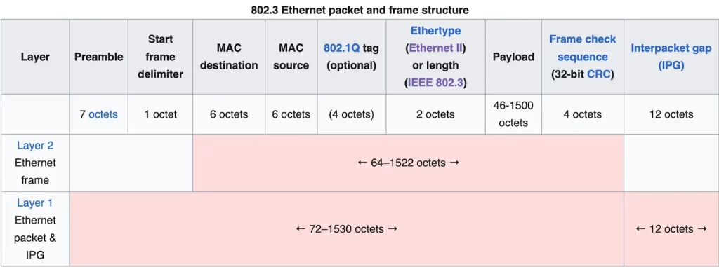
*Ethernet packet – Physical layer
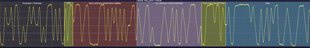
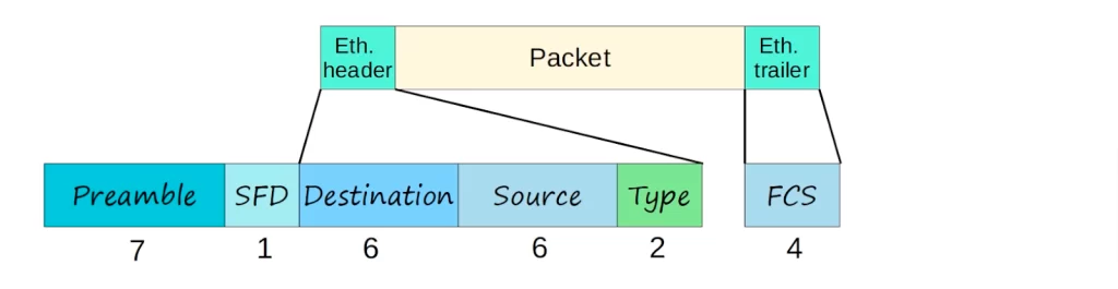
An Ethernet packet starts with a seven-octet preamble and one-octet start frame delimiter (SFD).
The preamble and SFD are used for synchronization and to allow the receiving device to be prepared to receive the rest of the data in the packet.
*Ethernet frame – Data Link layer
An Ethernet frame is a payload of an Ethernet packet. An Ethernet frame is a Data Link layer protocol data unit and uses the underlying Ethernet Physical layer transport mechanisms.
Each Ethernet frame starts with an Ethernet header, which contains destination and source MAC addresses as its first two fields (6 bytes + 6 bytes). These are followed by an optional 802.1Q field (4 bytes). This is followed by the type field (2 bytes).
Next, after the header, the middle section of the frame is payload/L3 packet (46-1500 bytes) including any headers for other protocols (e.g., Internet Protocol). The frame ends with a frame check sequence (FCS), which is a 4-byte/32-bit cyclic redundancy check used to detect any in-transit corruption of data.
The maximum size of an Ethernet frame in IEEE 802.3 is 1518 octets (1 octet = 1 byte = 8 bits). This includes 14 octets of header, 4 octets of the FCS, and 1500 octets of payload. The minimum size of an Ethernet frame is 64 octets, which includes 14 octets of header, 4 octets of the FCS, and 46 octets of payload.
There are some variations to the maximum frame size in IEEE 802.3. For example, the IEEE 802.3ac standard allows for a maximum frame size of 1522 bytes to accommodate the inclusion of an 802.1Q VLAN tag.
>Ethernet frame header
The Ethernet header features destination and source MAC addresses, an optional IEEE 802.1Q tag or IEEE 802.1ad tag, and the EtherType field.
The destination field is the Layer 2 address to which the frame is being sent. The source field is the Layer 2 address of the device which sent the frame.
The final field in the Ethernet header is the type. The EtherType field is two octets long and it can be used for two different purposes. If the size of the Ethernet payload is 1500 and below, the EthernetType field indicates the size (length) of the payload (in octets). If the size of the Ethernet payload is 1536 and above, the type field indicates which protocol is encapsulated in the payload of the frame (usually Internet Protocol). When used to indicate type, the length of the frame is determined by the location of the interpacket gap and valid frame check sequence (FCS).
In other words, the Ethernet Type field indicates the Layer 3 protocol used in the encapsulated packet, which is almost always Internet Protocol, IP version 4 or IP version 6. However, sometimes this is a length field, indicating the length of the encapsulated data, depending on the version of Ethernet.
The IEEE 802.1Q tag or IEEE 802.1ad tag, if present, is a four-octet field that indicates VLAN membership and IEEE 802.1p priority. The first two octets of the tag are called the Tag Protocol IDentifier (TPID). The TPID identifies the type of frame, and can be either 0x8100 for IEEE 802.1Q or 0x88a8 for IEEE 802.1ad. So an EtherType value of 0x8100 means the frame is tagged, and the true EtherType/Length is located after the Q-tag. The TPID is followed by two octets containing the Tag Control Information (TCI), the IEEE 802.1p priority (PCP and DEI) and VLAN id. The Q-tag is followed by the rest of the frame.
The fields of the 802.1Q tag are more thoroughly explained in the lesson Configuring trunk ports on Cisco switches, section “VLAN tagging (ISL, 802.1Q)”.
>Ethernet frame payload
An Ethernet frame encapsulates a L3 packet payload within a header and trailer.
Payload is a variable-length field. Its minimum size is governed by a requirement for a minimum frame transmission of 64 octets. With header and FCS taken into account, the minimum payload is 42 octets when an 802.1Q tag is present and 46 octets when absent. When the actual payload is less than the minimum, padding octets are added accordingly. IEEE standards specify a maximum payload of 1500 octets. Non-standard jumbo frames allow for larger payloads on networks built to support them. (https://en.wikipedia.org/wiki/Ethernet_frame)
>Trailer/frame check sequence (FCS)
The Ethernet trailer has only one field, the FCS, frame check sequence. FCS is used by the receiving device to detect any errors that might have occurred in transmission.
Ethernet frame types (versions)
As noted, there are several types of Ethernet frames. Two main ones are Ethernet II and IEEE 802.3. The following paragraphs up to “Let’s summarize” are taken from https://en.wikipedia.org/wiki/Ethernet_frame. Then we go back to using Jeremy’s IT Lab video lesson as our key reference (see Key references).
Ethernet II framing (also known as DIX Ethernet, named after DEC, Intel and Xerox, the major participants in its design), defines the two-octet EtherType field in an Ethernet frame, preceded by destination and source MAC addresses, that identifies an upper layer protocol encapsulated by the frame data. Most notably, an EtherType value of 0x0800 indicates that the frame contains an IPv4 datagram, 0x0806 indicates an ARP datagram, and 0x86DD indicates an IPv6 datagram.
As the industry-developed Ethernet II standard went through a formal IEEE standardization process, the EtherType field was changed to a data length field in the new 802.3 standard.
In order to allow some frames using Ethernet II framing and some using the original version of 802.3 framing to be used on the same Ethernet segment, EtherType values must be greater than or equal to 1536 (0x0600). That value was chosen because the maximum length of the payload field of an Ethernet 802.3 frame is 1500 octets (0x05DC). Thus if the field’s value is greater than or equal to 1536, the frame must be an Ethernet II frame, with that field being a type field. If it’s less than or equal to 1500, it must be an IEEE 802.3 frame, with that field being a length field. Values between 1500 and 1536, exclusive, are undefined. This convention allows software to determine whether a frame is an Ethernet II frame or an IEEE 802.3 frame, allowing the coexistence of both standards on the same physical medium.
Let’s summarize
Ethernet packet – preamble and SFD
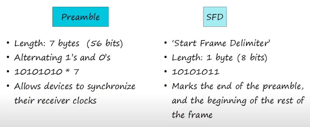
>The preamble:
*It is 7 bytes or 56 bits long (there are 8 bits in 1 byte).
*Its bit pattern is 10101010* 7 (one byte seven times).
*The purpose of this field is that it allows devices to synchronize their receiver clocks, to make sure they’re ready to receive the rest of the packet and the data inside.
>The SFD (start frame delimiter):
*Its length is 1 byte or 8 bits.
*Its bit pattern is 10101011, similar to each byte of the preamble but the last bit is a 1, not a 0.
*It indicates the end of the preamble and the beginning of the rest of the packet.
Ethernet frame – header + L3 packet + trailer
*Ethernet header
The Ethernet header consists of three fields: destination (6 bytes), source (6 bytes), and type (2 bytes), 14 bytes in total.
>Ethernet header – destination and source
The destination and source fields specify the devices sending and receiving the frame. The addresses used in Ethernet are the destination and source MAC addresses. MAC stands for media access control. The MAC address is assigned to the device when it is made. The MAC address is a 6-byte, or 48-bit, address of the physical device.
>Ethernet header – type/length
The last field of the Ethernet header is the type or length field. This field can be used to represent either the length of the encapsulated packet or the type of the encapsulated packet.
*It is 2-bytes or 16-bits in length.
*If the value in the field is 1500 or less, that means the field is indicating the length of the encapsulated packet in bytes.
*A value of 1,536 or greater in this field indicates the type of the encapsulated packet, which is usually Internet Protocol version 4 or version 6, and then the length is determined via other methods.
For example, a value of 0x0800, which is written in hexadecimal, is equal to 2048 in decimal. The 0x in front of 0800 is used to indicate hexadecimal. 2048 is greater than 1536, of course, and it identifies that the encapsulated packet is an IPv4 packet.
IPv4 = 0x0800 (hexadecimal) = 2048 in (decimal)
IPv6 = 0x86DD (hexadecimal) = 34525 (decimal)
0x86DD, which is equal to 34525 in decimal, indicates that the encapsulated packet is an IPv6 packet.
*Ethernet trailer – Frame Check Sequence (FCS)

*The only field of the Ethernet trailer is the FCS, which stands for frame check sequence.
*It is 4 bytes or 32-bits in length.
*The purpose of the FCS field is to detect corrupted data by running a CRC algorithm over the received data.
*CRC means cyclic redundancy check. Cyclic refers to cyclic codes. Redundancy refers to the fact that these 4 bytes at the end of the message enlarge the message without adding any new information, so they are redundant. And check refers to the fact that it checks or verifies the data for errors.
*Padding bytes
The minimum size of an Ethernet frame (header + L3 packet + trailer) is 64 bytes.
The size of the Ethernet header is 14 bytes, and the trailer/FCS is 4 bytes, both totalling 18 bytes.
64 bytes minus the 18 bytes of the header and trailer equals 46 bytes.
Therefore, the minimum payload size is 46 bytes.
If the payload packet is less than 46 bytes, padding bytes are added, and these bytes are all 0s. For example, if you send a 34-byte packet, 12 bytes of padding will be added.
MAC addresses
*A MAC address is a 6-byte, or 48-bit, physical address assigned to the device when it is made. This is different from an IP address, which you assign in the CLI when you configure the device.
*You might hear the term burned in address or BIA to refer to the MAC address. This is because the address is “burned-in” to the device as it is made.
*The MAC address is globally unique, no two devices in the world should have the same MAC address. Although, exceptionally, there are MAC addresses known as locally-unique MAC addresses which do not have to be globally unique.
*The first 3 bytes (24 bits) of the MAC address are the OUI, which stands for organizationally unique identifier. The OUI is assigned by the Institute of Electrical and Electronics Engineers (IEEE) Registration Authority to the company making the device. Cisco, for example, will have various OUIs which only Cisco can use, and other makers will have their own OUIs which only they can use.
*The last 3 bytes, the second half of the MAC address, are unique to the device itself.
*MAC addresses are written as a series of 12 hexadecimal characters.
Here’s a simple network comprised of three PCs connected to a switch. Note, in general, switches (like routers) have one MAC address per port.
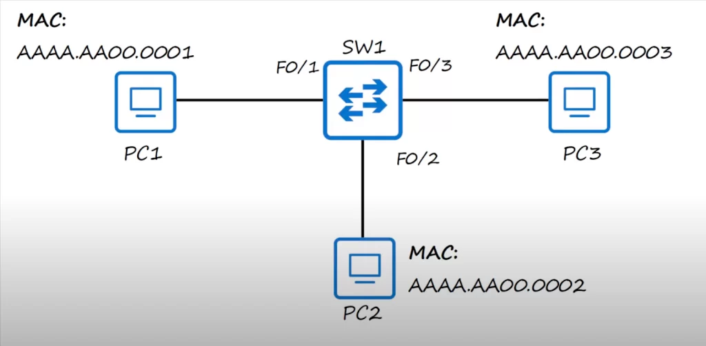
Notice the interface names for the switch, F0/1, F0/2, and F0/3. F means FastEthernet, so these are 100 Megabit per second interfaces.
You may also see MAC addresses written with periods or hyphens after every other digit, so for example PC1’s MAC address would be AA.AA.AA.00.00.01.
The MAC address for each PC is shown, but note this is a simplified way of writing the MAC addresses. A real MAC address might look something like this: 00-B0-D0-63-C2-26. Also, an abbreviation is used in our discussion, e.g., referencing only the last four digits of the MAC address.
Unicast frames
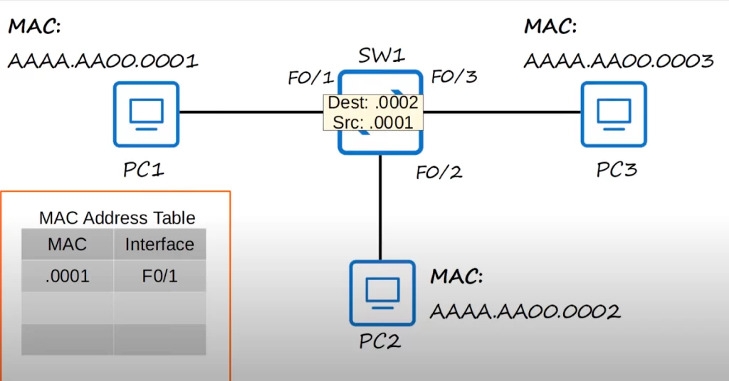
Let’s say PC1 with a source MAC address of .0001 wants to send a frame to PC2 with a destination MAC address of .0002. This kind of frame is called a unicast frame, a frame destined for a single target, PC2 in this case.
PC1 sends the frame through its NIC (network interface card), which is connected to SW1, and SW1 receives the frame.
MAC address table / dynamic MAC addresses
After SW1 receives the frame, it looks at the source MAC address field of the frame and then uses that information to learn where PC1 is.
As you can see, SW1 adds the MAC address AAAA.AA00.0001 to its MAC address table, and it associates that MAC address with its F0/1 interface. This is known as a dynamically learned MAC address, or just dynamic MAC address, because it wasn’t manually configured on the switch, the switch learned it itself.
Every switch will keep a MAC address table and will fill the MAC address table dynamically by looking at the source MAC address of frames it receives.
Since SW1 received a frame from source MAC address AAAA.AA00.0001 on its F0/1 interface, SW1 knows that it can reach that MAC address on that interface, and adds the MAC address to its MAC address table. This is how switches dynamically learn where each device on the network is, by looking at the source MAC address of the frame.
Unknown unicast / flooding
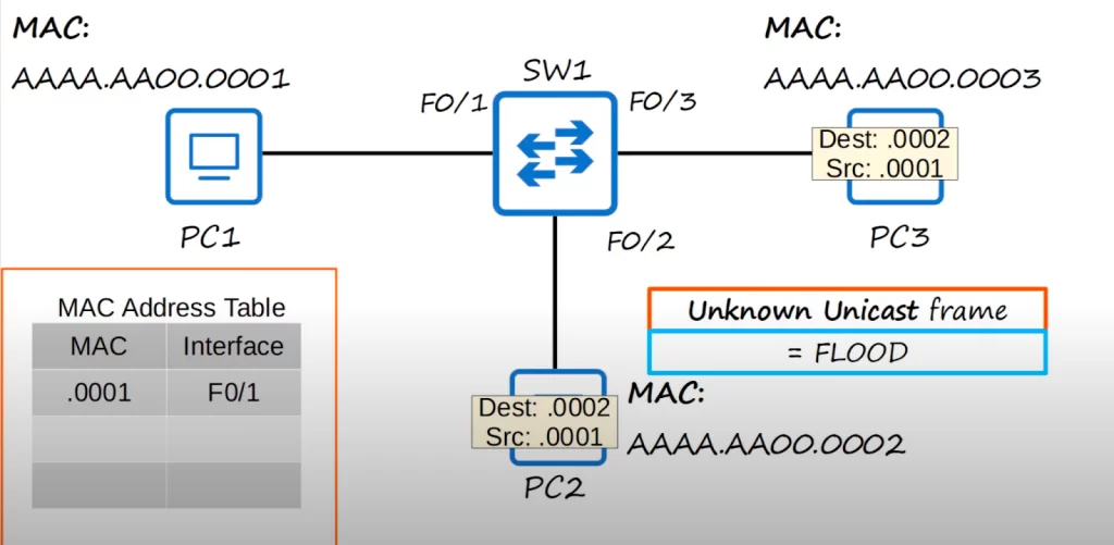
The destination of the frame is AAAA.AA00.0002, but SW1 does not know how to reach .0002. This frame is called an unknown unicast frame, because it is a frame for which the switch has no entry in its MAC Address table.
Because the switch does not know how to reach the destination, the switch has only one option, that is, to flood the frame. Flood means to forward the frame out of all of its interfaces, except the interface it received the frame on. SW1 copies the frame and sends it out its F0/2 and F0/3 interfaces.
That would look like this.
PC3 ignores (drops) the packet, because the destination MAC address does not match its own MAC address. PC2, however, receives the packet, and then processes it normally, up the OSI stack.
Let’s say PC2 then wants to send some data to PC1, maybe a reply to what PC1 sent to PC2.
Notice, below, the destination and source addresses of the frame are reversed. PC2 sends the frame out of its network interface, and SW1 receives it. SW1 looks at the source MAC address of the frame, and then adds the MAC address to its MAC address table, associating it with the F0/2 interface.
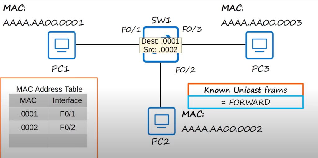
Known unicast / forwarding
This time SW1 does not flood the frame. This is known as a known unicast frame, because the destination is already in the switch’s MAC address table. Whereas unknown unicast frames are flooded, known unicast frames are forwarded to the destination. PC1 then processes the frame up the OSI stack, through the de-encapsulation process.
On Cisco switches, these dynamic MAC addresses are removed from the MAC address table after 5 minutes of inactivity. So if PC1 did not send any traffic for over 5 minutes, SW1 would remove the MAC address to clean out the MAC address table. Of course, if PC1 sent traffic again, SW1 would dynamically learn its MAC address again.
MAC learning and frame flooding / forwarding review
Let’s look at another example, this time with two switches.
PC1 wants to send some information to PC3. The source MAC address of the packet is .0001 and the destination is .0003. PC1 sends the frame out of its network interface and it arrives at SW1. SW1 learns PC1’s MAC address from the source address field of the frame and associates it with the interface on which it was received, F0/1. But SW1 still does not know where PC3 is. So SW1 floods the frame out all of its ports, except the one it was received on. In this case it will flood the frame out of F0/2 and F0/3.
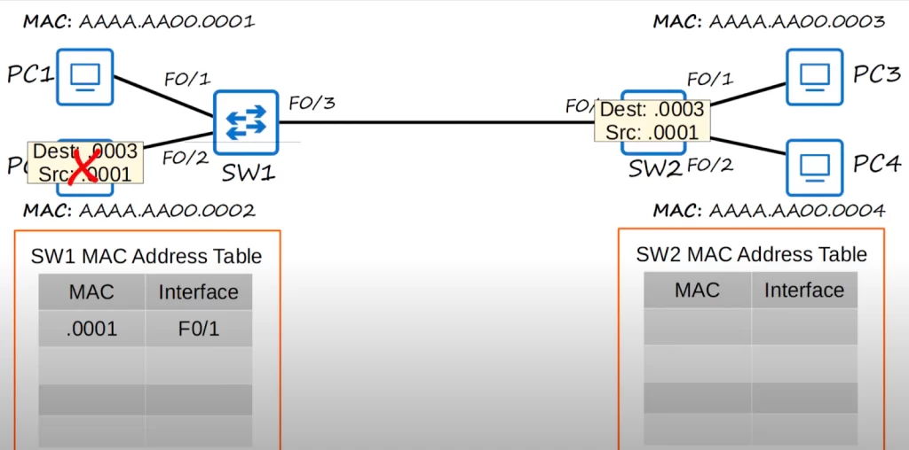
PC2 drops the frame because the destination MAC Address doesn’t match its own MAC address.
Just like SW1 did, SW2 uses the source MAC address field of the frame to dynamically learn PC1’s MAC address (.0001) and the interface it can use to reach PC1, F0/3. This is the interface that SW2 will use to reach PC1.
SW2 received a unicast frame, that is a frame destined for a single device, but SW2 does not know how to reach that device, because it is not in its MAC address table.
So SW2 floods the frame out of interfaces F0/1 and F0/2. PC4 drops the frame because the destination MAC address does not match its own. PC3, however, receives the frame, as the destination MAC address matches its own MAC address.
Let’s say that PC3 is going to send a reply back to PC1. The destination and source MAC address fields are reversed. PC3 sends the frame out of its network interface, and it is received by SW2. SW2 learns PC3’s MAC address, and enters the MAC address and the corresponding interface in its MAC address table.
SW2 already has an entry for the destination MAC Address .0001 in its MAC address table, so there is no need to flood the frame. Instead, it is forwarded normally out of the corresponding interface in the MAC address table, which is F0/3. The frame is received by SW1, which adds an entry for PC3’s MAC address in its MAC address table, with the interface F0/3, since that’s where it received the frame.
Finally, since SW1 already has an entry for the destination MAC address in its own MAC address table, SW1 forwards the frame out of the corresponding interface, and it reaches its destination, PC1.
Practice quiz questions
Quiz question 1
Which field of an Ethernet frame provides receiver clock synchronization?
A. preamble
B. SFD
C. Type
D. FCS
The answer is A, preamble. The preamble is a series of 1s and 0s (7 bytes of 10101010) which allows the receiving device to synchronize its receiver clock. The SFD signifies the end of the preamble. The type field indicates the type of packet encapsulated within the frame. The FCS is used to detect errors that occurred during transmission.
You can find four more practice questions for this lesson in Jeremy’s Ethernet LAN Switching (Part 1) video, cited below.
Key references
Note: The resources cited below (in the “Key references” section of this document) are the main source of knowledge for these study notes/this lesson, unless stated otherwise.
Free CCNA | Ethernet LAN Switching (Part 1) | Day 5 | CCNA 200-301 Complete Course
Related content
Compliance frameworks and industry standards
How data flow through the Internet
How switches forward frames – ARP
How to break into information security
IT career paths – everything you need to know
Job roles in IT and cybersecurity
Network security risk mitigation best practices
The GRC approach to managing cybersecurity
The penetration testing process
The Security Operations Center (SOC) career path
Back to DTI Courses


