This post discusses the Open Systems Interconnection (OSI) Model. It constitutes Lesson 2 of the module How data flow through the Internet. Key concepts discussed in this post include the OSI model Physical layer, Data Link layer, Network layer, Transport layer, Session layer, Presentation layer, Application layer, and data encapsulation/de-encapsulation.
- Learning objectives
- The Open Systems Interconnection (OSI) Model
- Layer 1: Physical layer (the wire) – transporting bits
- Layer 2: Data Link layer – hop to hop delivery
- Layer 3: Network layer – end to end delivery
- Layer 4: Transport layer – service to service delivery
- Layers 5, 6, 7 – Session, Presentation, Application
- Data encapsulation/de-encapsulation
- Key lesson takeaways
- Key references
You may also be interested in How data flow through the Internet.
Learning objectives
- Understand what is the OSI model
- List the layers of the OSI model and describe their functions
- Understand the types of network devices that operate at each layer of the model
- Know what protocols operate at each layer of the model
- Understand the addressing schemes of layers 2, 3, and 4
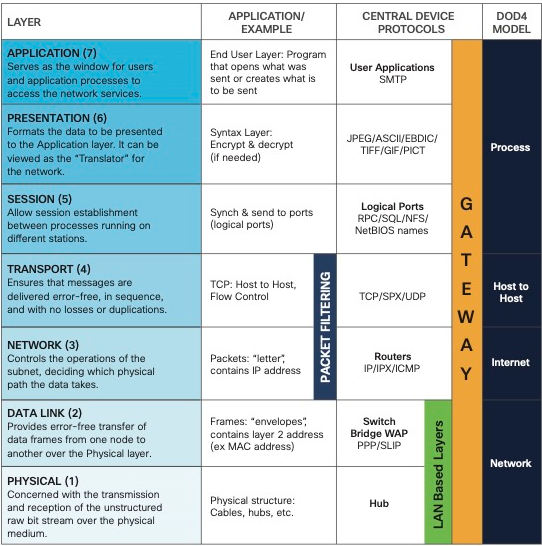
The Open Systems Interconnection (OSI) Model
The purpose of networking is to allow two hosts to share data with one another. To share data, hosts must follow a set of rules. According to the Open Systems Interconnection Reference Model, the rules of networking are divided into seven layers: Application, Presentation, Session, Transport, Network, Data Link, and Physical. Remember the layers of the OSI model by remembering the mnemonic, All People Seem To Need Data Processing.
Each layer of the OSI model serves a specific function that contributes to the overall goal of allowing two hosts to share data with one another. Each layer uses its own addressing scheme to accomplish its goal. There are various devices and protocols which operate at specific layers of the OSI model which serve in accomplishing each layer’s goal.
Layer 1: Physical layer (the wire) – transporting bits
Computer data exist in the form of bits, 0’s and 1’s. The physical layer transports bits between hosts. Anything that contributes to moving bits from one host to another is a Layer 1 technology, e.g., Ethernet cable, serial cable, Wi-Fi, repeaters, and hubs.
The actual format of the data on the “wire” can vary with each medium. In the case of Ethernet, bits are transferred in the form of electric pulses. In the case of Wifi, bits are transferred in the form of radio waves. In the case of Fiber, bits are transferred in the form of pulses of light. (Ed Harmoush, February 26, 2019)
More generally, the Physical layer:
- Defines the physical characteristics of the medium used to transfer data between devices (e.g., voltage levels, maximum transmission distances, and cable specifications)
- Converts digital bits into electrical signals (for wired connections) or radio signals (for wireless connections)
Layer 2: Data Link layer – hop to hop delivery
Layer 2 interacts with the wire – it puts bits on the wire and retrieves bits from the wire. Whatever the wire connects to on a PC is considered a Layer 2 item. So the NIC (Network Interface Card) which the wire is connected to on the computer is considered Layer 2. Switches and Wi-Fi access cards are also considered Layer 2 technologies.
Layer 2 exists to move bits from one NIC to another, i.e., to accomplish hop to hop delivery. To accomplish this goal, Layer 2 uses an addressing scheme known as the MAC (Media Access Control) address. Every NIC has a unique MAC address which allows data to flow from one NIC to the next, i.e., from one hop to the next.
A MAC address is 6 bytes or 48 bits in length (1 byte = 8 bits = 1 octet). MAC addresses are written as a series of 12 hexadecimal characters. MAC addresses can be represented with dashes (Windows machines) or colons (Linux machines) separating 6 pairs of digits, e.g., 00-B0-D0-63-C2-26, or with dots separating three groups of four hexadecimal digits (Cisco machines), i.e., 9465.9C3B.8AE5.
Often communication between hosts requires multiple hops. We need to jump across multiple routers to get to the target host. Each of those routers is connected to a wire using a NIC, therefore each of those NICs has its own MAC address.
Layer 2 will handle taking data from the first MAC address and delivering it the next MAC address – from NIC to NIC. Layer 2 handles the hop to hop delivery of data.
More generally, the Data Link layer:
- Provides node to node connectivity and data transfer (e.g., PC to switch, switch to router, and router to router)
- Defines how data is formatted for transmission over a physical medium (e.g., Copper UTP cables)
- Detects and possibly corrects transmission errors on the Physical layer
- Uses L2 addressing
Layer 3: Network layer – end to end delivery
Layer 3 handles the end to end delivery of data, i.e., the flow of data from host to host across networks. To accomplish this goal, Layer 3 uses its own addressing scheme known as the IP address.
Routers are a Layer 3 technology because they aid in moving data from host to host across networks. Anything with an IP address can be considered to exist on Layer 3 of the OSI model.
Why do we need both an IP address and a MAC address to move data on a network?
Each addressing scheme serves a different purpose.
Let’s say one host needs to send some data to another host on a different network. The first host is going to add some Layer 3 information to that data. That Layer 3 information is going to include the source IP address and the destination IP address.
The first host (computer) knows that the first step will be getting that data to the first router, which will prompt the computer to add Layer 2 information to that data, and that Layer 2 information is going to have a source MAC address of the computer’s NIC and a destination MAC address of the first router’s NIC. That’s what’s going to get this information to the first router. Once it gets there we can discard that Layer 2 information. Remember, the purpose of that Layer 2 header was to get this construct to the first hop.
The first router now adds a new Layer 2 header containing the MAC addresses of the new source NIC (the first router) and the new destination NIC (the second router). That’s what’s going to take this packet to the next router. And here once again we can get rid of that Layer 2 information. Again, the purpose of that Layer 2 header was to get the packet from one NIC to the next. Since it did that successfully we no longer need it.
This process of hop to hop delivery will repeat. Finally the last router in the sequence will add the final Layer 2 header which will deliver the packet to the end host’s NIC. Once the packet gets to the final host, the Layer 2 header can be discarded. Likewise, the Layer 3 header can be discarded because the purpose of that header was to bring the data from end to end.
More generally, the Network layer:
- Provides connectivity between end hosts on different networks
- Provides logical addressing (IP addresses)
- Provides path selection between source and destination
Layer 4: Transport layer – service to service delivery
The overall goal of the Transport layer of the OSI model is service to service delivery.
Suppose we have a computer. It has an IP address and a MAC address. Whoever is using this computer likely has a web browser open and is browsing the web. At the same time that user is running some sort of chat program, such as Slack or Discord or IRC (Internet Relay Chat). The user might also be running some sort of online game. Each of those programs is meant to send and receive data over the wire.
All that data will be destined to the computer’s Layer 3 header to accomplish end to end delivery and to its Layer 2 header to accomplish hop to hop delivery. But how do we make sure that the right program receives the right packets? Enter Layer 4.
Layer 4 is there to distinguish data streams. It’s going to take all the incoming data and make sure that the right program receives the right data. Just like layers 3 and 2 each had an addressing scheme to perform their function, Layer 4 is also going to use its own addressing scheme to accomplish its goal of service to service delivery.
Layer 4’s addressing scheme involves two sets of ports for TCP (Transmission Control Protocol) and UDP (User Datagram Protocol):
- 0-1023: these are well-known ports that are assigned by the Internet Assigned Numbers Authority (IANA) and are used for common protocols, such as HTTP (port 80), HTTPS (port 443), and FTP (port 21).
- 1024-65535: these are registered ports that are also assigned by IANA, but they are available for general use.
Any port number that is not in one of these ranges is considered to be a dynamic port. Dynamic ports are used for applications that need to dynamically allocate ports, such as peer-to-peer file sharing applications.
TCP and UDP are both Layer 4 protocols whose function is to distinguish network streams from one another. TCP and UDP are two different strategies for accomplishing the goal of Layer 4. TCP favors reliability and UDP favors efficiency.
Here are some examples of how port sets are used in Layer 4:
- A firewall might use a port set to block all traffic except for traffic that is destined for well-known ports. This would prevent unauthorized users from accessing applications that are running on the protected hosts.
- A web server might use a port set to listen for connections on multiple ports. This would allow the web server to handle multiple types of traffic, such as HTTP and HTTPS, on the same host.
- A load balancer might use a port set to distribute traffic across multiple servers. This would improve the performance of the servers by spreading the load evenly across them.
Every program that’s expected to receive or send data on the wire is going to be associated with a particular port number. Then when data arrives on the wire it’s going to include a Layer 4 header in addition to the Layer 3 and the Layer 2 headers … that Layer 4 header will indicate which particular program should be receiving that data. And that’s what Layer 4 is going to use to make sure the right program receives the right 1’s and 0’s. (OSI Model Lesson 2, Part 2)
Let’s take a closer look at this communication process.
Suppose we have a client and three servers. Each piece of software on a computer is assigned a predefined port number which correlates to the underlying network application. bank.com is listening for a secure web request using https which is assigned TCP port 443. And the server for site.com is responding to general web requests using http which by default listens on TCP port 80. And a chat server is running IRC which runs on UDP port 6667.
A connection from our client to site.com would look like this: our client sends out a packet to the server of site.com. It includes a source port of 9999. That’s the port that the client randomly selected for this particular connection. The destination of this packet is the IP address of site.com, going to TCP port 80 which is the http application.
For each request made by the client, the client is going to choose a random port number to use as the source port for the connection. The randomly selected source port is the port the client will listen to for the response to the original request – meaning when the server responds to the client it is going to include this port number as the destination (and the new source port, port 80).
For all connections there is always a source port and a destination port that are involved. The destination port is typically governed by the application in use and the source port is randomly selected by the client. This process occurs for each connection made by a client to a server (such as a web browser or an IRC chat server). This process allows a client to make multiple connections to the same server.
In each case a client selects a new random source port, and when the server responds, it responds to that specific source port number. This way the data streams are kept isolated from each other. TCP and UDP protocols will ensure that the right application gets the right data. Each time you open a new tab your web browser generates a new random source port. This is why each browser tab does not accidentally display the data from another tab.
More generally, the Transport layer:
- Segments and reassembles data for communications between end hosts
- Breaks large chunks of data into smaller segments that are more easily sent over the network and less likely to cause transmission problems
- Provides host to host communication (end to end communication)
- Provides process to process communication for applications (service to service delivery)
Layers 5, 6, 7 – Session, Presentation, Application
The Session, Presentation, and Application layers of the OSI model handle the final steps of transferring data through a network for display to end users.
Layer 5 (Session): controls ports and sessions (dialogues) between communicating hosts; establishes, manages/maintains, and terminates connections between the local application (e.g., web browser) and the remote application (e.g., YouTube).
Layer 6 (Presentation): translates Application layer data (data in application format) to the appropriate network format/ensures that data are in a usable format; where encryption of sent data and decryption of received data occurs.
Layer 7 (Application): human-computer interaction layer, where applications can access the network services. L7 protocols such as HTTP and HTTPS interact with software applications such as web browsers. L7 protocols govern the identification of communication partners and the synchronization of communication (same-layer interaction between hosts).
Back when the OSI model was originally conceived, each of these layers had a distinct function independent from the rest. However, currently the distinction between these layers is somewhat vague. Every application is free to implement the functions of layers 5, 6, and 7 as it chooses. Therefore often these three layers are simply considered as a single universal Application layer. In fact, there is another popular Internet communication model known as the TCP/IP model, which groups these three layers into one single encompassing layer.
From a purely network engineering perspective, the distinction between layers 5, 6, and 7 is not particularly significant. The most critical layers to understand how data flow through the Internet are layers 1 through 4. The distinction would become more significant if you were involved in software engineering. Many network engineers simply refer to these layers as L5-7 or L5+ or L7. For now/here, we’re going to follow the TCP model’s lead and simply consider all three of these layers as the Application.
Data encapsulation/de-encapsulation
The process of data encapsulation and de-encapsulation: what’s happening when hosts are communicating with each other using this networking stack.
Sending/encapsulation
When a computer has data to send, it encapsulates it in a IP header which will include information like the Source and Destination IP addresses of the two “ends” of the communication. The IP Header and Data are then further encapsulated in a MAC address header, which will include information like the Source and Destination MAC address of the current “hop” in the path towards the final destination. (Ed Harmoush, February 26, 2019)
Suppose a computer application needs to send data to a server on a different network. What that host is going to go through is what’s known as the encapsulation process.
That data will be first sent to Layer 4. Layer 4 is going to add a header to that data which can facilitate the goal of Layer 4 which is service to service delivery. In this case it is a TCP header which is going to include the source port and destination port for this particular data. The construct of a Layer 4 header plus data is known as a segment.
That segment is going to be passed down the OSI stack to the next layer, Layer 3, the Network layer. And the Network layer is going to add another header to this data. This header is going to facilitate the goal of Layer 3 which is end to end delivery, meaning, in this header you’ll have something like a source IP address and a destination IP address. The construct of a Layer 3 header and its data is known as a packet.
Notice that inside the data of the packet is the Layer 4 header that was above it. But from Layer 3’s perspective it doesn’t know or doesn’t care what’s inside that data. It’s simply a bunch of 1’s and 0’s that need to be delivered to the other end. Either way Layer 3 will then take that packet and hand it off to Layer 2, and Layer 2 will once again add another header to that data to accomplish Layer 2’s goal of hop to hop delivery – meaning this header will include something like a source MAC address and a destination MAC address. The construct of a Layer 2 header and its ensuing data is known as a frame. And that frame gets converted into 1’s and 0’s and finally put on the wire.
Receiving/de-encapsulation
On the other side, the receiving host is going to do the opposite process. It’s going to do de-encapsulation – meaning it’s going to take those 1’s and 0’s off the wire to convert them back into their frame.
Layer 2 is going to look at the Layer 2 header to make sure that it is indeed addressed to this host’s NIC. If it is, it’s going to discard that header and pass that up the stack. Then Layer 3 is going to look at the IP header to confirm that it is indeed addressed to this host’s IP address. If it is, it’s going to discard that Layer 3 header and pass it up the stack to the Transport layer. Layer 4 will then take a look at the Layer 4 header to identify the port that this data is destined to and will deliver the data to the appropriate application. The application can then finally process the data.
All models are wrong
The adage “all models are wrong, but some are useful” applies to networking.
We’ve mentioned that networking devices operate at specific layers of the OSI model. For example, switches operate at Layer 2 and routers operate at Layer 3. What that means is that they only look into the datagram up to their respective layer. So, e.g., switches are only looking at the frame, at the Layer 2 header to make a decision. They’re not looking inside the data payload into the Layer 3 and Layer 4 headers.
We’ve also discussed that there are various protocols which operate at specific layers. For instance the IP protocol is a Layer 3 protocol. TCP and UDP are Layer 4 protocols.
But there are exceptions.
For example, if you take a router which typically operates at Layer 3 but configure access list on that router now that router is looking into the Layer 4 header to make a decision. Here, the router is not purely a Layer 3 device anymore.
We’ve been talking about IP addresses and MAC addresses as independent functions, and they are. But there is a protocol that ties these together, ARP, the Address Resolution Protocol. ARP links an IP address to a MAC address, which means ARP doesn’t purely fit in Layer 3 nor does it purely fit in Layer 2.
Key lesson takeaways
- The OSI model is a way to conceptualize what is required for data to flow through the Internet
- Layer 1: Physical layer – transporting bits
- wires, cables, Wi-Fi, repeaters, hubs
- Layer 2: Data Link layer – hop to hop delivery
- MAC addresses, switches
- Layer 3: Network layer – end to end delivery
- IP addresses, routers, any device with an IP address
- How layers 2 and 3 work together to move data across different hops to get data from one end to another
- Layer 4: Transport layer – service to service delivery
- distinguish data streams
- addressing scheme – ports – 0-65535, TCP or UDP
- 0-65535 – TCP – favours reliability
- 0-65535 – UDP – favours efficiency
- servers listen for requests to pre-defined ports
- clients select random port for each connection – response traffic will arrive on this port
- Layers 5, 6, 7 – Session, Presentation, Application
- the distinction between these layers is somewhat vague
- other networking models combines theses three layers into one
- L1-L4 are the most important to understand how data flow through the Internet
- OSI data encapsulation/de-encapsulation
- how hosts communicate with each other using the OSI networking stack
Key references
Ed Harmoush. (February 26, 2019). OSI Model (PracNet)
OSI Model: A Practical Perspective – Networking Fundamentals – Lesson 2a
OSI Model: A Practical Perspective – Part 2 – Networking Fundamentals – Lesson 2
Related content
Compliance frameworks and industry standards
How to break into information security
IT career paths – everything you need to know
Job roles in IT and cybersecurity
Network security risk mitigation best practices
The GRC approach to managing cybersecurity
The penetration testing process
The Security Operations Center (SOC) career path
Back to DTI Courses


