The Network Time Protocol (NTP) synchronizes clocks. These study notes look at how NTP is used to synchronize the time of day across network devices. This lesson covers topic 4.2 of the CCNA exam topics list (Section 4.0 IP Services) which says you must be able to “Configure and verify NTP operating in a client and server mode”.
First, we look at some basic settings, how to configure the timezone, daylight savings time, the date, and time on a router or switch. Then we look at basic NTP configuration. We look at how the ntp server and ntp master commands are used to configure NTP in a sample network consisting of three serially connected routers. Then we look at how to verify the configurations with the show ntp status and show ntp associations commands. Then we look at some NTP internals regarding how NTP defines the sources of time data (reference clocks) and how good each time source is (stratum). Finally, we look at typical enterprise configurations, with multiple ntp commands for redundancy and the use of loopback interfaces for high availability. We look at how to configure NTP on local devices to reference NTP servers that use an atomic clock as their reference source, with the configuration enabling local NTP servers as backups. And we look at how to configure a loopback interface on an NTP server. This post constitutes Issue 31 of my CCNA 200-301 study notes.
- Network Time Protocol (NTP) introduction
- Setting the time and timezone
- Basic NTP configuration
- NTP reference clock and stratum
- Redundant NTP configuration
- Using a loopback interface for better availability
- NTP commands review
- Key learnings
- Practice quiz questions
- Key references
You may also be interested in CCNA 200-301 study notes.
Network Time Protocol (NTP) introduction
Like CDP, LLDP, and syslog, NTP focuses more on managing the network devices themselves than on managing the network that devices create.
If the time of day is not synchronized across all network devices, then the log messages from routers and switches stored at a syslog server would be useless for troubleshooting network problems. This is because the log messages would not be in chronological order, making it difficult to determine the order in which events happened. Additionally, the timestamps on the log messages would be inaccurate, making it difficult to correlate events between different devices.
Network Time Protocol (NTP) provides a means for devices to synchronize their time-of- day clocks.
NTP provides protocol messages that devices use to learn the timestamp of other devices. Devices send timestamps to each other with NTP messages, continually exchanging messages, with one device changing its clock to match the other, eventually synchronizing the clocks. As a result, actions that benefit from synchronized timing, like the timestamps on log messages, work much better. (Odom, 2020, p. 476)
Benefits of synchronizing time across all network devices include:
- Improved troubleshooting: As mentioned above, synchronized time makes it easier to troubleshoot network problems by correlating log messages from different devices.
- Increased security: Synchronized time can help to improve network security by making it more difficult for attackers to spoof timestamps and manipulate log data.
- Reduced costs: Synchronized time can help to reduce costs by reducing the need for manual time synchronization and by improving the efficiency of network operations.
Setting the time and timezone
Set the device clock before enabling the NTP client function with the ntp server command. Set the date, time, timezone, and daylight savings time parameters and then enable NTP.
Example 9-7 shows how to set the timezone, daylight savings time, the date, and time. Two global commands are used to set the timezone and daylight savings time and one EXEC command is used to set the date and time on the router.
Example 9-7 Setting the Date/Time with clock set, Plus Timezone/DST (Odom, 2020, pp. 477-478)
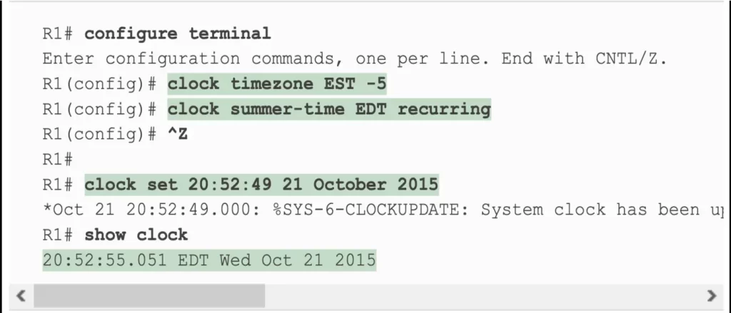
Start with the two global configuration commands before setting the time of day with the clock set EXEC command.
In the first configuration command, the clock timezone part defines the command (clock) and a keyword (timezone). The next parameter is the time zone of the device, up to four characters long. It is EST in this case. EST is an acronym for U.S. Eastern Standard Time. The next parameter is the hours-offset, the hours difference from Universal Time Coordinated. The range is from -12 to +13. It is -5 in this case, meaning this device is 5 hours behind UTC. Note, the hours-offset parameter can be followed by an optional minutes-offset parameter, the minutes difference from UTC. The range is from 0 to 59.
In the second configuration command, the clock summer-time part defines the command (clock) and a keyword (summer-time). The next parameter is the zone, which specifies the name of the summer time zone. In this case, the zone is EDT, which stands for Eastern Daylight Time. EDT and EST represent the same time zone, the Eastern Time Zone in North America, but they signify different points in the year.
- EDT (Eastern Daylight Time): Used during Daylight Saving Time (DST), i.e., during the summer months. During this period, clocks are set one hour forward compared to standard time.
- EST (Eastern Standard Time): Used during the rest of the year, outside of DST (usually fall and winter).
Finally, the recurring keyword specifies that the summer time configuration should be recurring over the years.
Next, set the time, day of the month, month, and year with the clock set EXEC command, as shown in Example 9-7.
Note, the show clock command lists the time as EDT. IOS interprets the time as typed in the command in the context of the time zone and daylight savings time.
Basic NTP configuration
NTP servers provide time information to clients, which then adjust their clocks to match. Repeated small adjustments maintain synchronization. The configuration of NTP servers can be simple or complex, depending on the level of security and redundancy needed.
Cisco has two ntp configuration commands that dictate how NTP works on a router or switch:
- ntp master {stratum-level}: NTP server mode—the device acts only as an NTP server, and not as an NTP client. The device uses its internal clock to know the time.
- ntp server {address | hostname}: NTP client/server mode—the device acts as both client and server. First, the device acts as an NTP client, synchronizing time with a server. Once synchronized, the device can then act as an NTP server to provide time information to other NTP clients.
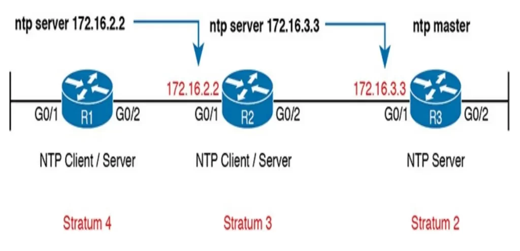
Figure 9-5 illustrates the basic configuration syntax and show commands:
- R3 acts as an NTP server only.
- R2 acts in client/server mode—first as an NTP client to synchronize time with NTP server R3, then as a server to supply time to NTP client R1.
- R1 acts in client/server mode—first as an NTP client to synchronize time with NTP server R2. (R1 acts as an NTP server, but no devices happen to reference it in this example.)
NTP can function with a single configuration command on each device.
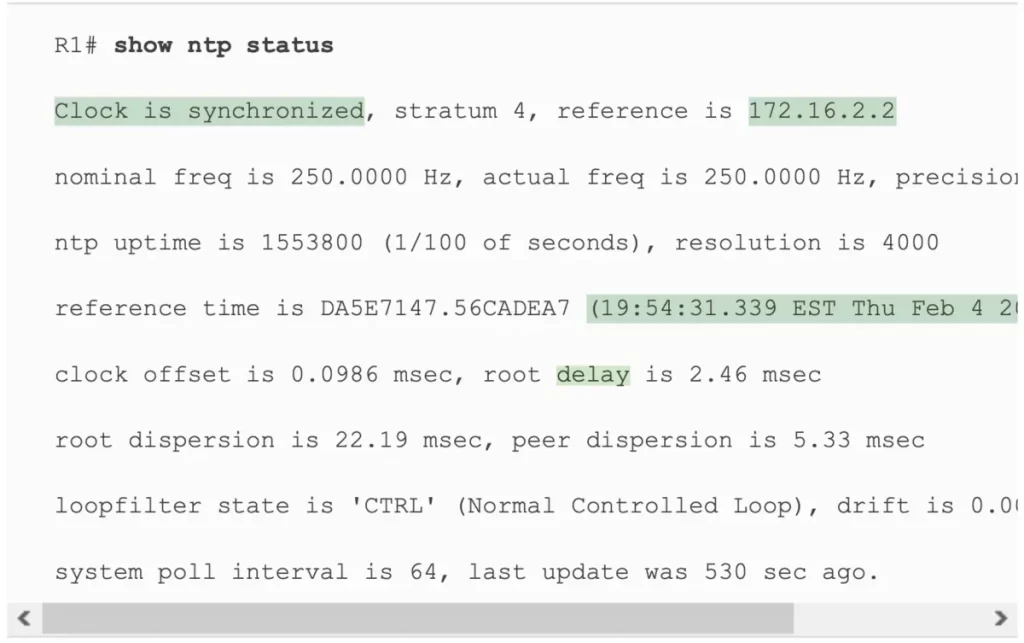
Let’s use the show ntp status command to check the configuration on R1. Example 9-9 lists the output. The first line of the output displays some important status items. First, the output shows a status of synchronized, which confirms the NTP client has completed the process of changing its time to match the server’s time. The output also shows the IP address of the server, which is R1’s reference clock, as configured in Figure 9-5.
Example 9-9 Verifying NTP Client Status on R1 (pp. 481-482)
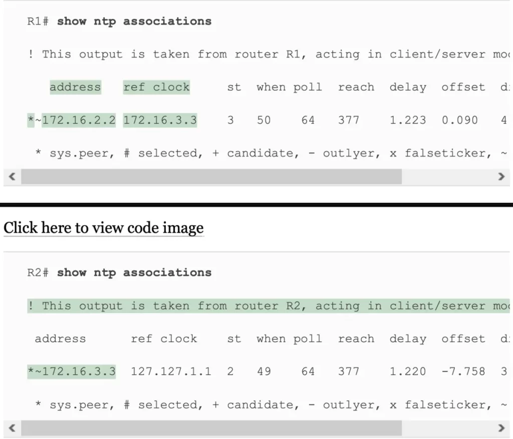
Next, let’s look at the show ntp associations command output from both R1 and R2, shown in Example 9-10. We can see all the NTP servers that the local device (client) can attempt to use, with status information about the association between the client and the various NTP servers.
R1 has one association (relationship with an NTP server) based on the one ntp server 172.16.2.2 configuration command on R1. The * means that R1 has successfully contacted the server. You can see similar data from the same command output for R2.
Example 9-10 Verifying NTP Client Status on R1 and R2 (pp. 482-483)
NTP reference clock and stratum
Who’s got the time?
Devices that operate in NTP client/server mode use the NTP client function to learn the time from an NTP server. Devices that operate solely as an NTP server, on the other hand, get their time from either internal device hardware or from some external clock using mechanisms other than NTP.
When configured with the ntp master command, a Cisco router/switch uses its internal device hardware to determine the time.
NTP servers and clients use a number to show the perceived accuracy of their reference clock data based on stratum level. The lower the stratum level, the more accurate the reference clock is considered to be. An NTP server that uses its internal hardware or external reference clock sets its own stratum level. Then, an NTP client adds 1 to the stratum level it learns from its NTP server, so that the stratum level increases the more hops away from the original clock source. (Odom, 2020, p. 484)
Looking back at Figure 9-5, the NTP primary server (R3) has a stratum of 2. R2 adds 1 to have a stratum of 3. R1 adds another 1, to have a stratum of 4. Devices use the stratum level to decide which NTP server they should refer to for information about the time.
Routers and switches use their internal reference clock as their default time source, and this clock is assigned a stratum level of 8 by default based on the default setting for the stratum level in the ntp master [stratum-level] command. In Figure 9-5, the ntp master 2 command set router R3’s stratum level to 2.
The ntp master command allows you to set a value from 1 through 15. NTP considers 15 to be the highest useful stratum level. A stratum of 16 means the time data is unusable, untrustworthy.
To check, let’s refer back to Example 9-10, the output for show ntp associations for R1 and R2 – based on the configuration in Figure 9-5. The output highlights details about reference clocks and stratum levels, as follows:
- R1: Per the configured ntp server 172.16.2.2 command, the show command lists 1) R2’s address of 172.16.2.2 (as the server for R1), 2) the reference clock (ref clock) for the server, i.e., R2’s reference clock, which is 172.16.3.3, and 3) R2’s stratum (st), 3.
- R2: Per the configured ntp server 172.16.3.3 command, the show command lists 1) R3’s address of 172,16,3,3 (as the server for R2), 2) R3’s ref clock as 127.127.1.1 — an indication that the server (R3) gets its clock internally, and 3) R3’s st (stratum), 2—consistent with the configured ntp master 2 command on R3.
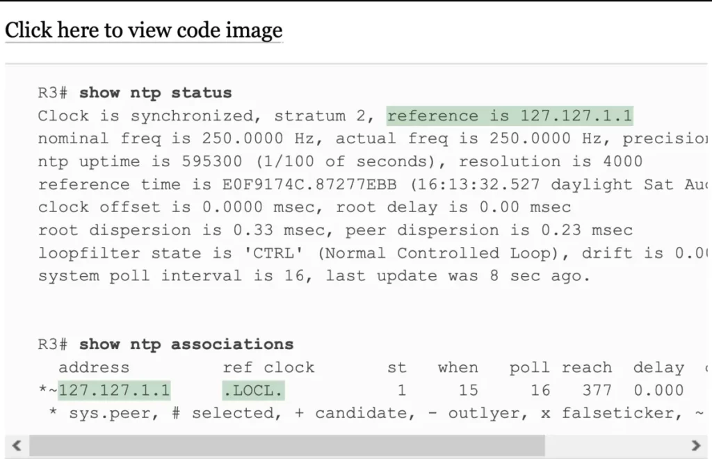
Let’s cross reference these settings with the outputs of show ntp status and show ntp associations on R3, the NTP primary server. See Example 9-11. Notice the ref clock of the 127.127.1.1 loopback address, indicating that this router gets its clock data internally. In the show ntp associations command output at the bottom, note a reference clock value of “.LOCL.” In effect, R3, per the ntp master configuration command, has an association with its internal clock.
Example 9-11 Examining NTP Server, Reference Clock, and Stratum Data (p. 486)
Redundant NTP configuration
Instead of using a networking device as the reference clock, an enterprise could use NTP to reference better time sources on the Internet or purchase a purpose-built NTP server that has better clocking hardware.
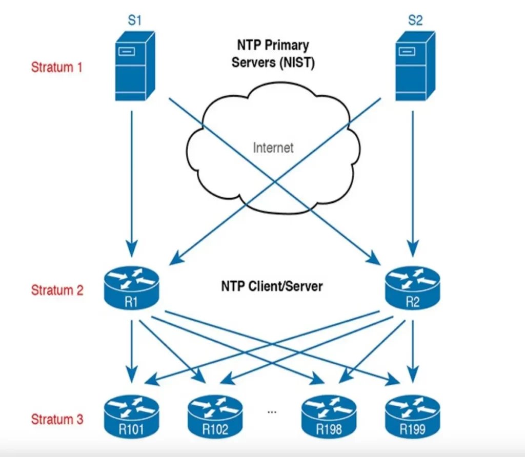
NTP can be configured to reference NTP servers that use an atomic clock as their reference source, like the NTP primary servers in Figure 9-6, which is run by the U.S. National Institute of Standards and Technology (NIST).
The common terms “NTP server mode” and “NTP client/server mode” are useful for describing how NTP servers work. However, the NTP RFCs 1305 and 5905 also use two other specific terms for similar ideas: “NTP primary server” and “NTP secondary server”.
An NTP primary server is a server that only acts as a server. It has a reference clock external to the device, and it has a stratum level of 1, like the two NTP primary servers shown in Figure 9-6. NTP primary servers are typically used as the time source for a network.
NTP secondary servers are servers that use client/server mode. They rely on synchronization with some other NTP server. NTP secondary servers typically have a stratum level of 2 or higher.
For good design, an enterprise’s NTP configuration should refer to at least two external NTP servers for redundancy. Additionally, only a few enterprise devices should refer to those external NTP servers and then act as both NTP client and server.
Most devices in the enterprise, like those shown at the bottom in Figure 9-6, would act as NTP clients. Example 9-12 shows the configuration on R1 and R2 in the figure to accomplish this design.
Example 9-12 NTP Configuration on R1, R2 per Figure 9-6:
ntp server time-a-b-nist.gov
ntp server time-a-g.nist.gov
In addition to referring to redundant NTP primary servers, some routers in the enterprise should be configured to act as backup NTP servers. This means that they will be ready to supply clock data to other devices if the primary NTP servers become unreachable.
If the only reference clock exists on the Internet and the Internet is disconnected for some reason, R1 and R2 will stop receiving NTP messages. After losing their reference clock, R1 and R2 could no longer be useful NTP servers to the rest of the enterprise.
So the configuration in Example 9-12 is not optimal. To overcome this potential problem, the routers can also be configured with the ntp master command, resulting in this logic:
1. Establish an association with the NTP servers per the ntp server command.
2. Establish an association with your internal clock using the ntp master stratum command.
3. Set the stratum level of the internal clock (per the ntp master {stratum-level} command) to a higher stratum level than the Internet-based NTP servers.
4. Synchronize with the best (lowest) known time source, which will be one of the Internet NTP servers in this case.
The configuration for this logic is shown in Example 9-13. Compared to Example 9-12, we just add the ntp master command. The ntp master 7 command was used to set a much higher stratum value for the backup NTP servers than that of NIST’s (primary NTP servers). This will cause R1 and R2 to use one of the NIST NTP servers when available and use the internal clock source only when connectivity to the NIST servers is lost.
Example 9-13 NTP Configuration on R1 and R2 to Protect Against Internet Failures:
ntp server time-a-b-nist.gov
ntp server time-a-g.nist.gov
ntp master 7
Using a loopback interface for better availability
NTP clients reference a specific IP address on the NTP server. That creates an availability issue. What if the interface that NTP clients reference fails. The IP address on that interface cannot be used to send and receive packets.
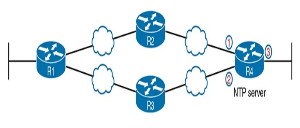
Consider the topology in Figure 9-7. R4 on the right acts as an NTP server and the other routers act as clients. We want to avoid a scenario in which a single interface failure on R4 causes NTP to fail.
We can use the router loopback interface to ensure clients consistently can reach R4.
Loopback interfaces are virtual interfaces internal to Cisco IOS, created via the command interface loopback number, where the number is an integer. Once configured, that loopback interface exists inside that router and is not tied to any physical interface. A loopback interface can be assigned an IP address, routing protocols can advertise about the subnet, and you can ping/traceroute to that address. (Odom, 2020, p. 491)
A loopback interface acts like a physical interface in many ways, but once configured, it remains in an up/up state as long as the router remains up.
Let’s do a small configuration change to add the loopback interface to the NTP configuration, which is based on the configuration in Figure 9-5. See Example 9-14.
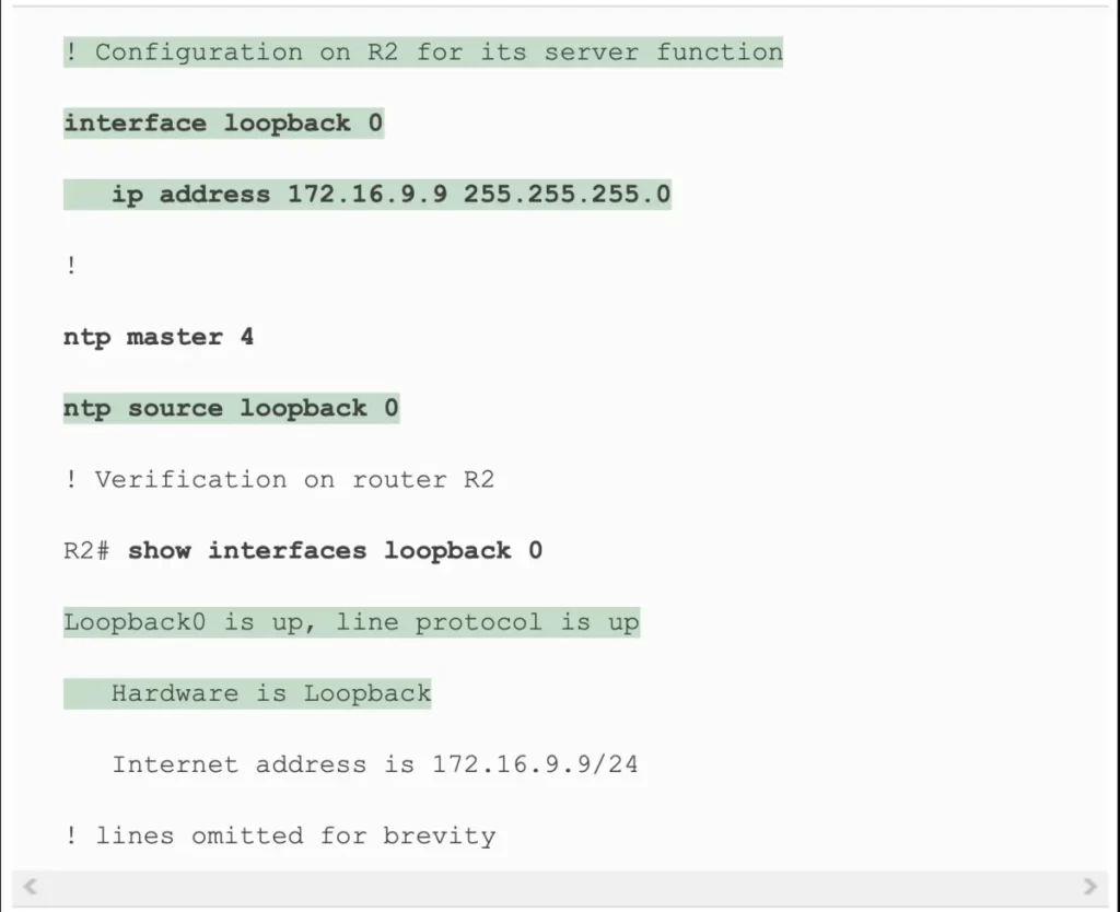
R1 acting as client now points to R2’s new loopback interface IP address of 172.16.9.9. R2 now has configuration for a new loopback interface (loopback 0). We also added a command that tells R2 to use that loopback 0 interface’s IP address as the source address when sending NTP packets.
Example 9-14 NTP Client/Server Configuration on R1 and R2 Using a Loopback Interface (pp. 492-493)
NTP commands review
>Setting the time and timezone (with examples):
Set the device clock before enabling the NTP client function with the ntp server command.
Two global commands are used to set the timezone and daylight savings time and one EXEC command is used to set the date and time on the router.
R(config)#clock timezone time-zone [+/-]hours-offset
→to name a timezone and define the +/- offset versus UTC
R(config)#clock timezone EST -5
R(config)#clock summer-time summer-time-zone recurring
→to name a daylight savings time for a timezone and tell IOS to adjust the clock automatically
R(config)#clock summer-time EDT recurring
R#clock set hh:mm:ss day month year
→to set the time, day of the month, month, and year
R#clock set 20:52:49 21 October 2015
R#show clock
→lists the time-of-day and the date for the device
>Basic NTP configuration:
Cisco has two ntp configuration commands that dictate how NTP works on a router or switch.
R(config)#ntp master [stratum-level]
→to configure the device as an NTP server and assign its local clock stratum level. When configured with this command, a Cisco device uses its internal device hardware to determine the time
Routers and switches use their internal reference clock as their default time source, and this clock is assigned a stratum level of 8 by default. The ntp master command allows you to set a stratum value from 1 through 15. NTP considers 15 to be the highest useful stratum level. A stratum of 16 means the time data is unusable, untrustworthy.
R(config)#ntp server {address | hostname}
→to configure the device as an NTP client by referring to the address or name of an NTP server
R#show ntp status
→shows current NTP client status in detail (synchronization, stratum, IP of server acting as a ref clock, etc.)
R#show ntp associations
→to see all the NTP servers that the local device (client) can attempt to use, with status information about the association between the client and the various NTP servers
>Redundant NTP configuration (example):
Devices that operate solely as an NTP server get their time from either internal device hardware or from some external clock using mechanisms other than NTP.
NTP can be configured to reference NTP servers that use an atomic clock as their reference source.
ntp server time-a-b-nist.gov
ntp server time-a-g.nist.gov
ntp master 7
>Using a loopback interface for better availability:
We can use the router loopback interface to ensure clients consistently can reach the NTP server.
R(config)#interface loopback loopback-number
→to create a loopback interface (at first use), and move to interface configuration mode for that interface
R(config)#ntp source interface-name/number
→to tell NTP to use the listed interface (by name/number) for the source IP address for NTP messages
R#show interfaces loopback loopback-number
→shows the current status of the listed loopback interface
Free CCNA | NTP | Day 37 Lab – Notes
Key learnings
- How to configure the time and timezone on a router or switch
- How to use the ntp server and ntp master commands to configure NTP in a network topology consisting of three serially connected routers
- How to verify the configurations with the show ntp status and show ntp associations commands
- How to configure NTP on local devices to reference NTP servers that use an atomic clock
- How to configure a loopback interface on an NTP server
Practice quiz questions
You can find four quiz questions and answers for this lesson in Odom, 2020, pp. 457-459.
Key references
Odom, W. (2020). Chapter 9. Device Management Protocols, CCNA 200-301 Official Cert Guide (pp. 455-518), Volume 2. Cisco Press.
Related content
Compliance frameworks and industry standards
How data flow through the Internet
How to break into information security
IT career paths – everything you need to know
Job roles in IT and cybersecurity
Network security risk mitigation best practices
The GRC approach to managing cybersecurity
The penetration testing process
The Security Operations Center (SOC) career path
Back to DTI Courses


