This lesson shows how to configure Layer 2 and Layer 3 EtherChannels, first by allowing dynamic protocols configured on a switch to create the channels, and then through manual (static) configuration. A Layer 2 EtherChannel is a group of switch ports which operate as a single interface, and a Layer 3 EtherChannel is a group of routed ports which operate as a single interface which you assign an IP address to. A routed port is a physical port on a switch that is configured as a Layer 3 interface. A routed port can be used to route traffic between VLANs or to the outside world. Routed ports is an alternative routing method to SVIs, which was discussed in VLANs Part 3. These study notes cover topic 2.4 of the official CCNA exam topics list, “Configure and verify (Layer 2/Layer 3) EtherChannel (LACP)” (Section 2. Network Access). This post constitutes Issue 18 of my CCNA 200-301 study notes.
- Configure and verify (L2/L3) EtherChannel (LACP/PAgP) – introduction
- EtherChannel load-balancing
- Configuration options for EtherChannel load distribution
- EtherChannel load-balancing verification and configuration
- EtherChannel protocols – PAgP, LACP, Static
- Configuring dynamic L2 EtherChannels
- EtherChannel configuration – PAgP
- EtherChannel configuration – LACP
- Configuring manual (static) L2 EtherChannels
- Manually configure negotiation protocol (PAgP or LACP)
- EtherChannel requirements (matching duplex, speed, etc.)
- EtherChannel verification (show etherchannel summary)
- EtherChannel verification (show etherchannel port-channel)
- Implementing Layer 3 EtherChannels
- Configuration/verification command review
- Practice quiz questions
- Key references
You may also be interested in CCNA 200-301 study notes.
Configure and verify (L2/L3) EtherChannel (LACP/PAgP) – introduction
EtherChannel allows you to group multiple physical interfaces together into a single logical interface so that the multiple physical interfaces function as a single interface.
Two neighboring switches can treat multiple parallel links between each other as a single logical link called an EtherChannel. Without EtherChannel, a switch treats each physical port as an independent port, applying MAC learning, forwarding, and STP logic per physical port. With EtherChannel, the switch applies all those same processes to a group of physical ports as one entity: the EtherChannel. Without EtherChannel, with parallel links between two switches, STP/RSTP would block all links except one, but with EtherChannel, the switch can use all the links, load balancing the traffic over the links. (Odom, 2020, p. 301)
Let’s demonstrate a problem.
We have two switches, ASW1 and DSW1. ASW stands for access switch, which is a Layer 2 switch that connects end-user devices to the network. DSW stands for distribution switch, which is a Layer 3 switch responsible for connecting the access layer to the core layer.
Let’s imagine ASW1 is connected to 40 end hosts all trying to access the Internet.
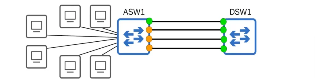
We have 4 links between ASW1 and DSW1. So you might think this provides ample bandwidth for traffic to flow to DSW1. But the connection between ASW1 and DSW1 is congested and end users are reporting problems.
Why is that? Because Spanning Tree Protocol (STP) can block links that are not actually redundant, which can reduce the overall bandwidth of the network.
If two switches are connected together with multiple links, all except one will be disabled by Spanning Tree. If all of ASW1’s interfaces were forwarding, Layer 2 loops would form between ASW1 and DSW1, leading to broadcast storms.
EtherChannel solves this problem by grouping the four physical links together into a single logical link. STP sees the EtherChannel as a single link, so it will not block any of the physical links in the group. This allows for the full bandwidth of the physical links to be utilized, while still preventing network loops.
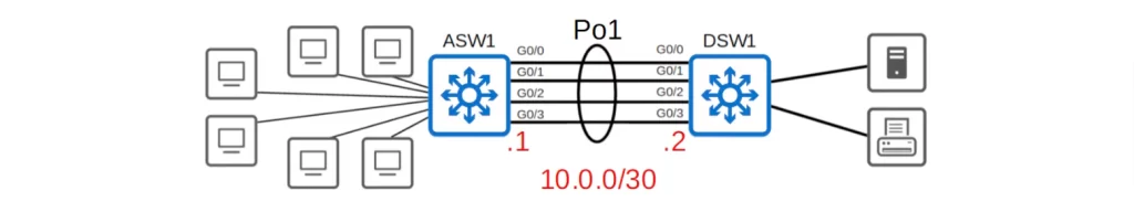
An EtherChannel is represented in network diagrams by drawing a circle around the interfaces that are grouped together, as shown:
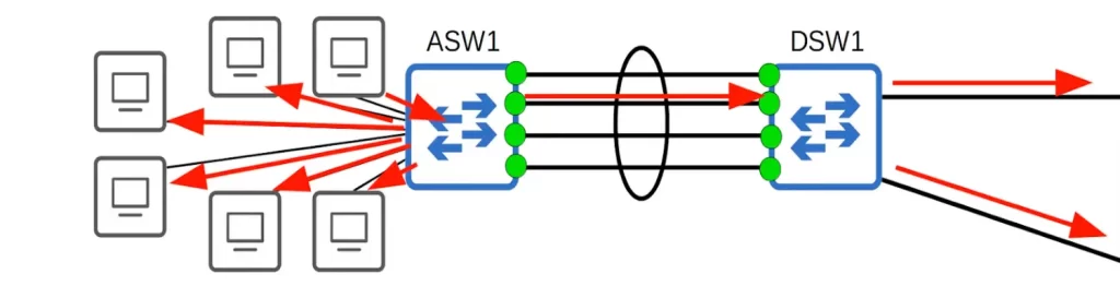
STP will treat this bundle of interfaces as a single interface. A Layer 2 loop will not form because this group of four links behaves as if it is a single link.
Let’s say a PC sends a broadcast frame. The frame is flooded out of all interfaces on ASW1 except the interface the frame was received on. All of the PCs connected to ASW1 will receive a copy of the frame.
How many copies of the frame will DSW1 receive? One. Although there are four physical interfaces, they behave as a single interface. The EtherChannel makes the four physical interfaces a single logical interface. ASW1 will not send four copies of the same broadcast frame out of a single interface.
Traffic using the EtherChannel will be load balanced among the physical interfaces in the group. An algorithm is used to determine which traffic will use which physical interface.
DSW1 received the broadcast frame. DSW1 will flood the broadcast frame out of all interfaces except the interface it was received on. So which interfaces will DSW1 forward the frame out of? Only two, in the direction of the red arrows on the right side of the above diagram.
Since the EtherChannel has grouped the four interfaces into one (logical) interface, and since switches do not flood broadcast frames out of the same interface that the frame was received on, the frame is not forwarded back to ASW1, and no Layer 2 loop is formed.
EtherChannel load-balancing
EtherChannel load balances based on flows. A flow is a communication between two nodes in the network, for example, between PC1 and SRV1.
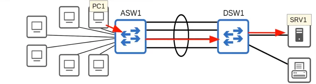
Suppose PC1 wants to send some data to SRV1. PC1 sends the frames to ASW1. Let’s assume ASW1 knows the MAC address of SRV1, so ASW1 will forward the frames out of the port channel to DSW1.
But which physical interface will ASW1 use to forward the frames? ASW1 will use an algorithm to calculate which physical interface the traffic will be sent on.
Let’s say ASW1 determines that the third interface from the top should be used (follow the red arrows). The next frame in the same communication flow from PC1 to SRV1 will use the same interface. Frames in the same flow are forwarded using the same physical interface. This consistency prevents frames from arriving out of order at their destination.
Now suppose PC1 wants to print something and initiates a separate communication flow with PR1. ASW1 will once again forward the frame using its virtual port channel interface. This time, ASW1 will make a separate calculation to determine which physical interface will be used for the flow. Let’s say ASW1 determines that the first interface from the top will be used for the flow.
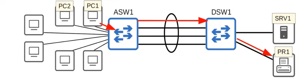
When PC1 sends another frame in the flow, the same member interface of the EtherChannel will be used to forward it.
If PC2 also wants to print something, ASW1 will do a new calculation to determine which physical interface in the EtherChannel will be used. ASW1 may decide to use the second interface from the top, for example. And we thus have a new communication flow.
Frames from PC1 to SRV1 will consistently use a certain interface. Frames from PC2 to SRV1 will consistently use a certain interface, which may or may not be the same interface used for traffic from PC1 to SRV1. You get the idea.
Configuration options for EtherChannel load distribution
EtherChannel performs load balancing by using different physical interfaces in the EtherChannel for different flows. EtherChannel load distribution makes the choice for each frame based on various numeric values found in the Layer 2, 3, and 4 headers.
Several inputs are used to calculate which physical interface should be used. These inputs can be changed (i.e., manually configured).
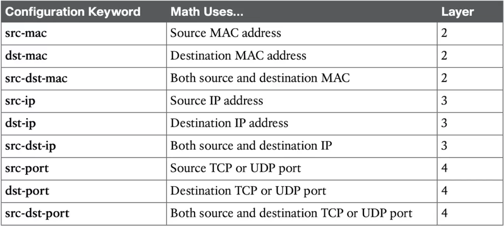
Here are the inputs that can be used for the calculations (see Table 10-4 EtherChannel Load Distribution Methods):
- Source MAC address. All frames with the same source MAC address use the same physical interface in the EtherChannel.
- Destination MAC address. All frames with the same destination MAC address use the same physical interface.
- Source and destination MAC addresses.
You can also configure the EtherChannel to select the interface based on the source IP address, the destination IP address, or both the source and destination IP addresses.
Some switches also support load-balancing based on the Layer 4 TCP or UDP port numbers. Not all switches support the use of all input types. Some switches may only support using MAC addresses, other switches may only support using IP addresses, and some switches may support using all the methods.
Table 10-4 EtherChannel Load Distribution Methods (Odom, 2020, p. 308)
EtherChannel load-balancing verification and configuration
Before getting into the configuration and verification, take note of some EtherChannel terminology. The terms EtherChannel, PortChannel, and Channel-group essentially mean the same thing. Cisco tends to use the term EtherChannel in concepts. IOS uses the channel-group configuration command, but then to display the channel-group status, IOS uses the show etherchannel command. Then the output of this show command refers to PortChannel.
Use the command show etherchannel load-balance to see the current load-balancing method.
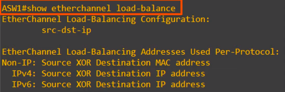
You can see the default load balancing method for this model of switch is based on the source and destination IP addresses. For example, all traffic going from 10.0.0.1 to 10.0.0.2 will always use a certain physical interface within the EtherChannel.
Notice, there is a more specific breakdown of inputs used for the load balancing calculations in the lower section of the above diagram:
- Non-IP: frames not encapsulating IP packets have no IP address. In this case the source and destination MAC addresses are used for load balancing decisions.
- Frames which encapsulate IP packets, whether IPv4 or IPv6, will load-balance based on the source and destination IP addresses.
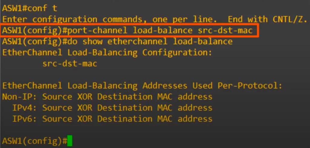
The port-channel load-balance method global command can be used to configure/change the load-balancing method. In this case the load-balancing method was changed to use the source and destination MAC addresses of the frame. Then we confirmed the configuration with show etherchannel load-balance.
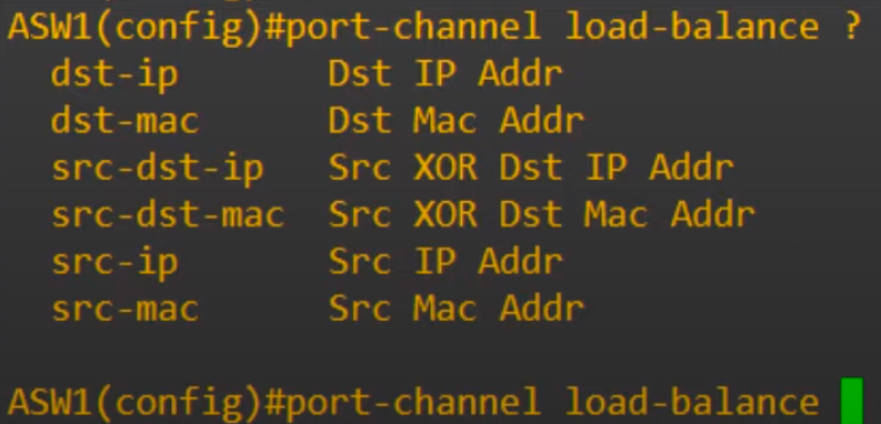
Here are the available load-balancing choices on this device.
EtherChannel protocols – PAgP, LACP, Static
Let’s get into creating an EtherChannel between two switches.
There are three methods of EtherChannel configuration.
The first method of EtherChannel configuration is PAgP, Port Aggregation Protocol. PAgP is a Cisco proprietary protocol. PAgP can only be used on Cisco switches. PAgP dynamically negotiates the creation and maintenance of the EtherChannel (DTP does a similar thing regarding trunk formation). Frames are sent to the neighboring switch to see if it wants to form an EtherChannel, and then the switches agree upon either forming an EtherChannel or not.
The second method of EtherChannel configuration is LACP, Link Aggregation Control Protocol. LACP is an industry standard protocol. LACP essentially does the same thing as PAgP: LACP dynamically negotiates the creation and maintenance of the EtherChannel (again, like DTP does for trunks).
Because it is an industry standard protocol, LACP does not run only on Cisco switches, so it can be used to form EtherChannels with switches from other vendors. Because of this, LACP is the preferred method of configuring EtherChannels.
Most Cisco Catalyst switches support the Cisco-proprietary PAgP and the IEEE standard LACP, which is based on IEEE standard 802.3ad.
The third and last method of EtherChannel configuration is static EtherChannel. In this case no protocol is used to determine if an EtherChannel should be formed. Instead, interfaces are statically configured to form an EtherChannel.
This is usually avoided, because you want the switches to dynamically maintain the EtherChannel (e.g., if there is a problem on an interface, you would want the switch to remove the interface from the EtherChannel).
LACP supports more links in a channel, 16, as compared to PAgP’s maximum of 8. With LACP, only 8 can be active at one time, with the other 8 waiting to be used should any of the other links fail.
Now let’s look into how to configure each of these three methods on L2 and L3 switches.
Configuring dynamic L2 EtherChannels
Cisco switches support two different configuration options that then use a dynamic protocol to negotiate whether a particular link becomes part of an EtherChannel or not. Basically, the configuration enables a protocol for a particular channel-group number.
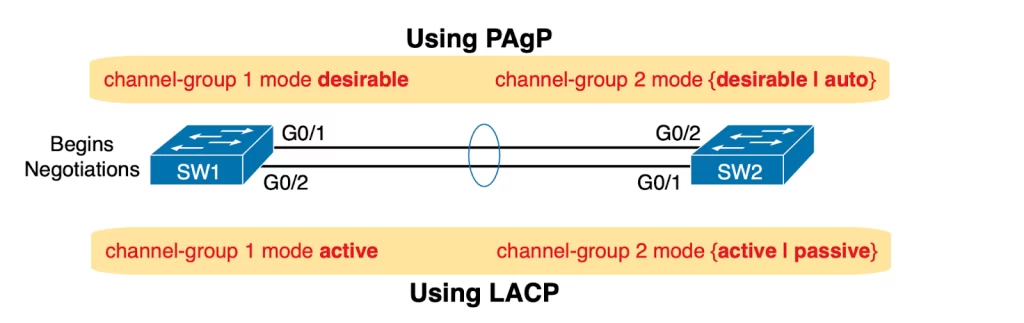
To configure either protocol, a switch uses the channel-group configuration commands on each switch, with a keyword that either means “use this protocol and begin negotiations” or “use this protocol and wait for the other switch to begin negotiations.”
The desirable and auto keywords enable PAgP, and the active and passive keywords enable LACP (see Figure 10-7). With these options, at least one side has to begin the negotiations. With LACP, at least one of the two sides must use active, and with PAgP, at least one of the two sides must use desirable.
EtherChannel configuration – PAgP
We can use the interface range command to configure all of the member interfaces at once, as in the following example. Configuring the interfaces all at once guarantees that the configurations on each member interface will match.
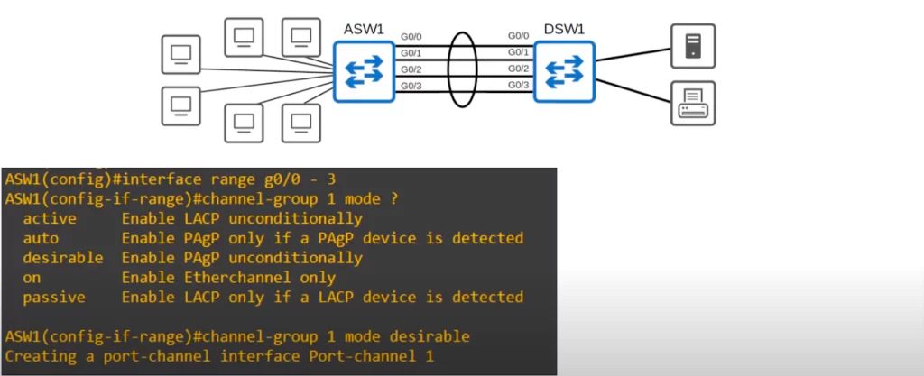
To configure the EtherChannel on ASW1 use the command CHANNEL-GROUP, followed by a number that identifies the virtual interface (the group number), MODE, and DESIRABLE, to enable PAgP.
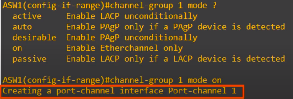
Note, first we used the question mark to see the mode options for the channel-group command, and five options returned.
auto and desirable are used for PAgP configuration.
active and passive are used for LACP configuration.
on is used for static EtherChannel configuration.
desirable mode actively tries to form an EtherChannel. auto mode will only form an EtherChannel if the other side is set to desirable, but not if the other side is set to auto.
For PAgP (for a functioning EtherChannel to form):
auto + auto = no EtherChannel
desirable + auto = EtherChannel
desirable + desirable = EtherChannel
You can see in the bottom line in the above diagram that the virtual port-channel interface was created, with the number we used in the channel-group command (port-channel 1).
You can see the interface in the following output of the SHOW IP INTERFACE BRIEF command, down at the bottom.
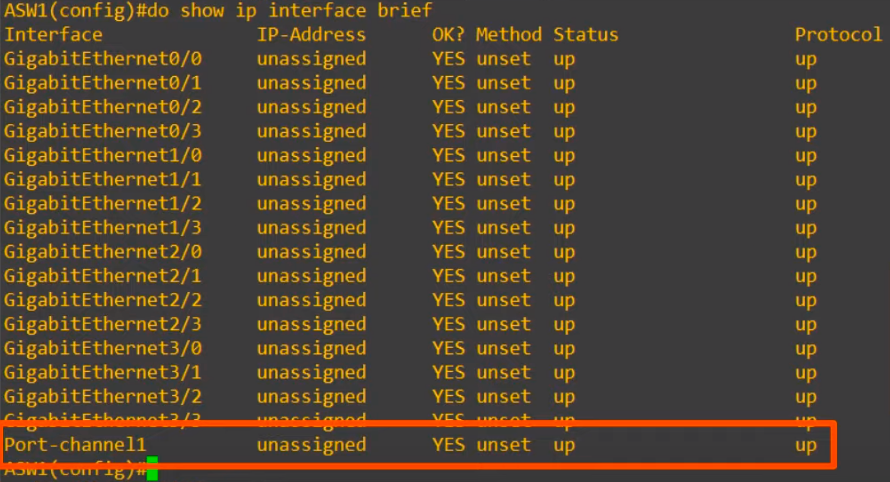
Notice that the CHANNEL-GROUP command is used to configure the EtherChannel, but the name of the virtual interface that is created is port-channel.
The channel group number has to match between interfaces on the same switch; however it does not have to match the channel-group number on the other switch. For example, channel-group 1 on ASW1 can form an EtherChannel with channel-group 2 on DSW1. The number is used to identify the virtual interface number on the local switch. Because you can have multiple EtherChannels on a single switch, a number to identify them is needed.
EtherChannel configuration – LACP
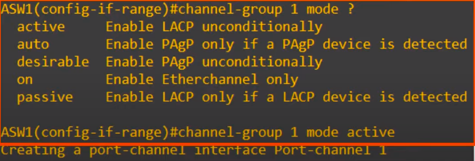
The LACP configuration command is basically the same as the PAgP configuration command, just the mode names are different.
Instead of desirable, LACP uses active mode. And instead of auto, LACP uses passive mode.
For LACP (for a functioning EtherChannel to form):
passive + passive = no EtherChannel
active + passive = EtherChannel
active + active = EtherChannel
In this case, ASW1 was configured as active. And again, the port-channel interface is created.
If both ends of the connection are configured in passive mode an EtherChannel will not be formed (though virtual interfaces will still be created, but not functioning as an EtherChannel).
Again, the channel-group number has to match between member interfaces on the local switch, but not the number on the neighbor switch.
Configuring manual (static) L2 EtherChannels
You can configure a static Layer 2 EtherChannel so that all the ports always attempt to be part of the channel by applying the channel-group configuration command to each physical interface on each switch, all with the on keyword and all with the same number. “The on keyword tells the switches to place a physical interface into an EtherChannel, and the number identifies the PortChannel interface number that the interface should be a part of” (Odom, 2020, p. 302).
To configure an EtherChannel manually, follow these steps:
Step 1: In interface configuration mode, configure each physical interface that should be in the channel with the channel-group number mode on command.
Step 2: Use the same number for all commands on the same switch, but the channel-group number on the neighboring switch can differ.
The command will create a port-channel interface, just as in dynamic EtherChannel configuration.
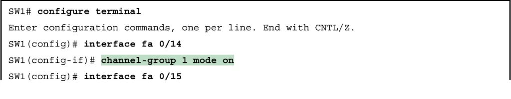
Figure 10-6 shows an example of an EtherChannel with two links between SW1 and SW2. The configuration shows SW1’s two interfaces placed into channel-group 1 (see Example 10-4 for the output of this configuration).
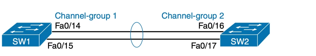
Example 10-4 Configuring and Monitoring EtherChannel (Odom, 2020, pp. 302-303)
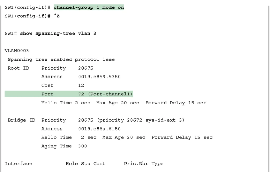
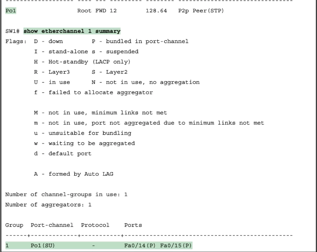
Notice, the show spanning-tree command lists Po1 (PortChannel1) as an interface. This interface was created because of the channel-group commands using the 1 parameter. STP is operating on the PortChannel1 interface, not on physical interfaces Fa0/14 and Fa0/15, so only that interface is listed in the output.
Also notice that the output of the show etherchannel 1 summary command lists as a heading “Port-channel,” with Po1 below it, and lists both Fa0/14 and Fa0/15 in the list of ports, with a (P) beside each. According to the legend, P means that the ports are bundled in the port channel, which is code for “these ports have passed all the configuration checks and are valid to be included in the channel” (Odom, 2020, p. 304).
Manually configure negotiation protocol (PAgP or LACP)
The CHANNEL-PROTOCOL command manually configures the EtherChannel negotiation protocol that the member interfaces should use.
Normally you would not need to configure the EtherChannel protocol. For example, if you configure CHANNEL-GROUP 1 MODE DESIRABLE or AUTO, the interface will automatically use PAgP. But you may want to know the command anyway.
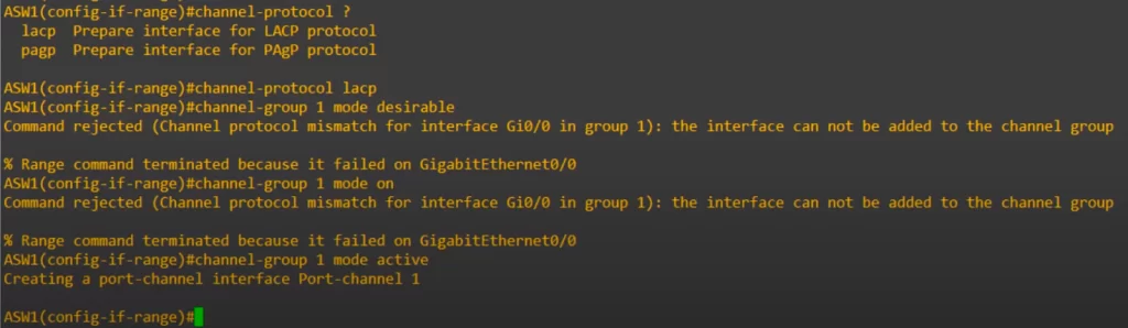
Note, the command only worked when the correct pair of protocol (LACP) and mode (active) were used to configure the interface.
After configuring the EtherChannel with a protocol, e.g., LACP, you can then configure the port-channel interface itself. Let’s use LACP as an example.
We do the same configurations on DSW1, so the EtherChannel is up and running.
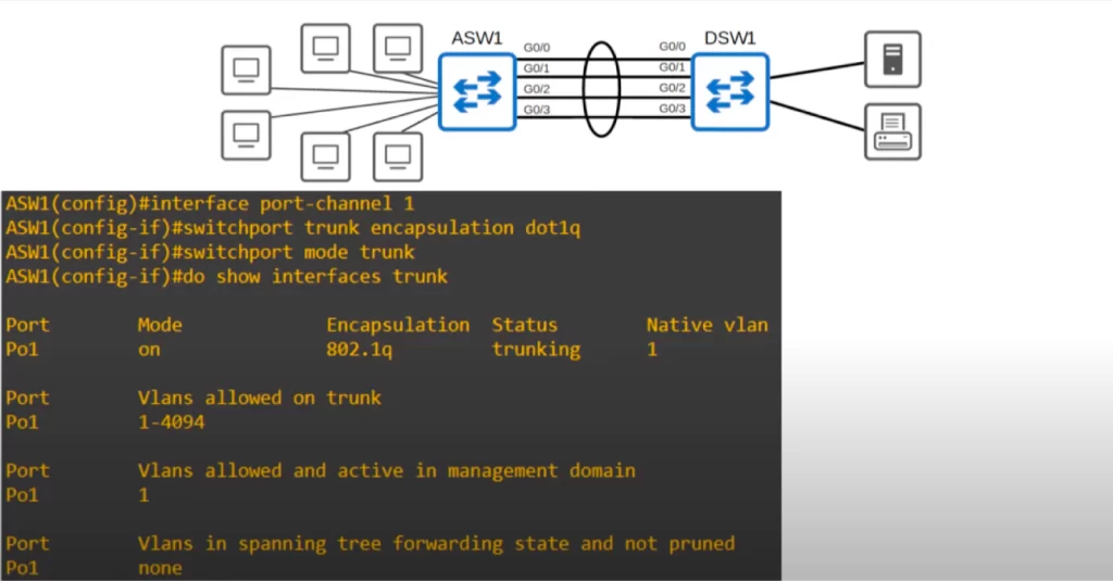
In the above diagram, the port-channel 1 interface was configured as a trunk from interface configuration mode. And the SHOW INTERFACES TRUNK command shows port-channel 1 (Po1) is a trunk. Notice, only the port-channel interface is listed, but the individual physical interfaces are not listed.
EtherChannel requirements (matching duplex, speed, etc.)
*Member interfaces, the physical interfaces in the EtherChannel, must have matching configurations:
- They must have the same duplex setting (half/full).
- They must have the same speed.
- They must have the same switchport mode (access or trunk). If they are a trunk, they must have the same allowed VLANs and native VLANs.
*If an interface’s configurations do not match the others, it will be excluded from the EtherChannel.
EtherChannel verification (show etherchannel summary)
The SHOW ETHERCHANNEL SUMMARY command is a very useful show command for verifying the status of an EtherChannel.
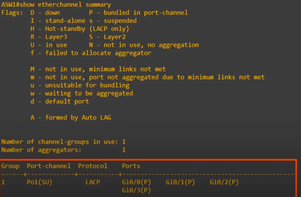
Notice the list of the port-channel interfaces on the switch.
Notice the two flags in brackets next to port-channel 1 (Po1): an upper-case S and upper-case U. According to the legend, we can understand that S means the switchport on ASW1 is a Layer 2 EtherChannel. U means in use, meaning the EtherChannel is active and being used.
Next to the physical ports, notice the flag P between brackets. This means that these ports are properly bundled in the port-channel.
These are the flags you would expect to see in an operational Layer 2 EtherChannel.
EtherChannel verification (show etherchannel port-channel)
The SHOW ETHERCHANNEL PORT-CHANNEL is another helpful show command. You can use it to see the number of ports in the port-channel and to see which protocol is being used.
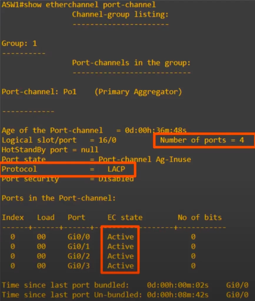
Notice, this command allows you to see the channel-group mode, active in this case because the CHANNEL-GROUP 1 MODE ACTIVE command was used earlier.
Let’s see how Spanning Tree is affected when EtherChannel is configured.
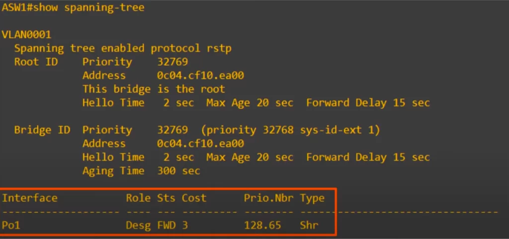
Notice, only the port-channel interface is listed, the physical interfaces do not appear at all in the output of this command. Spanning Tree is treating the four physical interfaces on ASW1 as a single logical interface. Instead of blocking three of them, they can all forward and receive traffic, without running the risk of creating Layer 2 loops.
Implementing Layer 3 EtherChannels
Routed interfaces can be used with a single point-to-point link between pairs of Layer 3 switches or between a Layer 3 switch and a router. However, most designs are deployed using at least two links between each pair of distribution and core switches, as shown in Figure 17-6.
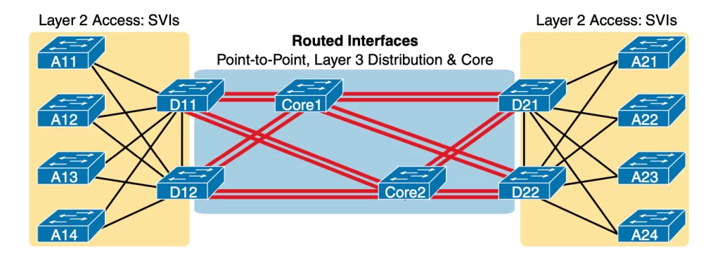
While each individual port in the distribution and core could be treated as a separate routed port, it is better to combine each pair of parallel links into a Layer 3 EtherChannel. Without using EtherChannel, you can still make each port on each switch in the center of the figure be a routed port. It works. However, once you enable a routing protocol but don’t use EtherChannels, each Layer 3 switch will now learn two IP routes with the same neighboring switch as the next hop—one route over one link, another route over the other link. (Odom, 2020, p. 464)
It makes more sense to use a Layer 3 EtherChannel with multiple parallel links between two switches. This way, each pair of links acts as one Layer 3 link. This way, each pair of switches has one routing protocol neighbor relationship with the neighbor, rather than two, and each switch learns one route per destination per pair of links, rather than two. This way, IOS can often achieve better balancing of the traffic than the balancing that occurs with the use of multiple IP routes to the same subnet.
Let’s replace ASW1 and DSW1 with multilayer switches. Instead of a Layer 2 connection between ASW1 and DSW1, let’s use a Layer 3 connection.
Using Layer 3 connections between switches eliminates the need to use Spanning Tree in a network.
If we deploy L3 routed ports to connect four switches interconnected in a mesh, all interfaces will be up and forwarding, none will have to be disabled due to Spanning Tree.
If we are using EtherChannel, L2 loops can still occur if multiple switches are connected together in a loop. For example, look at the following diagram. All the connections between switches are using EtherChannel, but if we do not block any of the port-channel interfaces, broadcasts can still loop around the switches like this and cause a broadcast storm.

However, if all of the connections between the switches were made using routed ports instead of Layer 2 switchports, there is no need to run Spanning Tree at all. Since routed ports do not forward Layer 2 broadcasts, no Layer 2 loops can be formed.
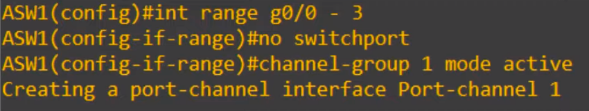
Let’s see how to configure a Layer 3 EtherChannel with a dynamic EtherChannel
First, we enter interface range config mode for the member interfaces. Next, we use the NO SWITCHPORT command to make them Layer 3 routed interfaces. Next, we use the CHANNEL-GROUP command to enable LACP.
Next, we use SHOW RUNNING-CONFIG to check the configuration.
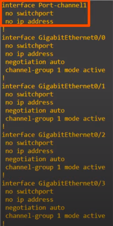
Notice, the created port-channel interface has the NO SWITCHPORT command applied to it automatically.
We are making a Layer 3 EtherChannel, so we need an IP address.
The IP address should be configured on the port-channel interface:
ASW1(config-if-range)#int po1
ASW1(config-if)#ip address 10.0.0.1 255.255.255.252
Now, let’s again check the SHOW ETHERCHANNEL SUMMARY command.
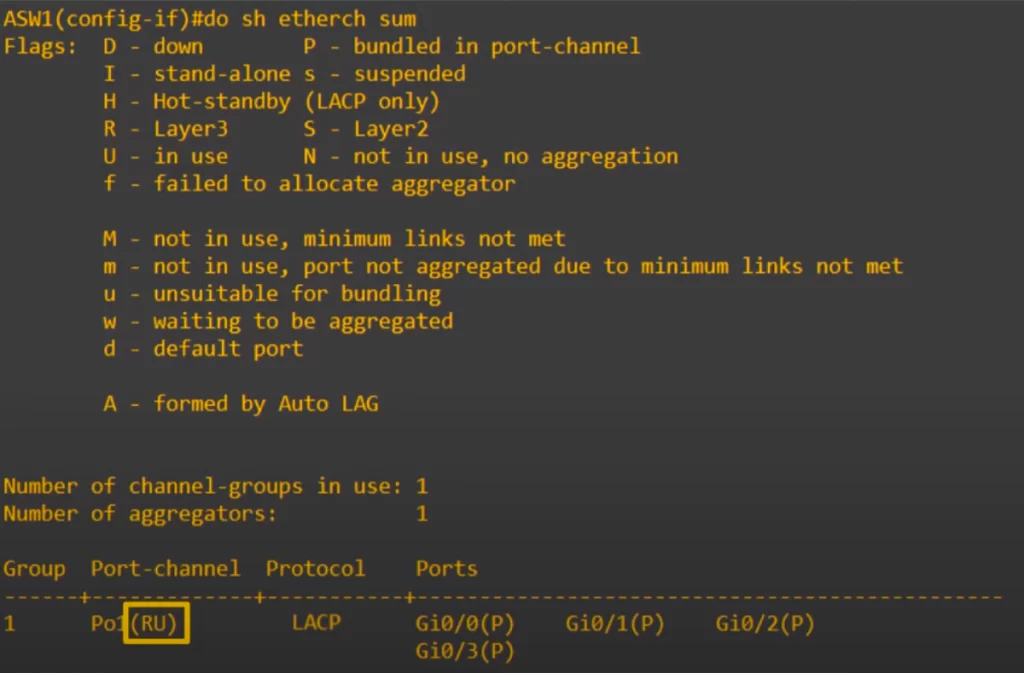
The only difference compared to the previous output using the SHOW ETHERCHANNEL SUMMARY command is that instead of the S flag, it has the R flag. R refers to L3, meaning a L3 EtherChannel. R stands for routed port.
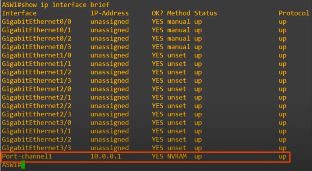
In the output of SHOW IP INTERFACE BRIEF, we can see the IP address configured on port-channel 1.
ASW1 and DSW1 are now like two routers connected together, and spanning-tree is not running on the connection between them.
Traffic will now be load-balanced over the four member interfaces, like with the Layer 2 EtherChannel.
Let’s see how to configure a Layer 3 EtherChannel with a static EtherChannel
The following checklist shows the steps of configuring a Layer 3 EtherChannel, assuming a static definition.
Step 1. Configure the physical interfaces as follows, in interface configuration mode:
- Configure the member ports as Layer 3 interfaces by using the no switchport command on each physical port (to make each physical port a routed port).
- Assign the member ports to the Layer 3 EtherChannel (add each interface to the channel) using the channel-group number mode on command (in case of a static configuration). Use the same channel group number for all physical interfaces on the same switch, but the channel-group number can differ on the two neighboring switches.
Step 2. Configure the PortChannel (the Layer 3 EtherChannel) interface:
- Use the interface port-channel number command to move to port-channel configuration mode for the same channel number configured on the physical interfaces.
- Use the no switchport command to configure the port-channel interface as a routed port. (IOS may have already added this command.)
- Use the ip address address mask command to configure the address and mask.
Here is an example for configuring a Layer 3 EtherChannel with a static EtherChannel (see Figure 17-7). The configuration for a Layer 3 EtherChannel for SW1 in Figure 17-7 is shown in Example 17-12.
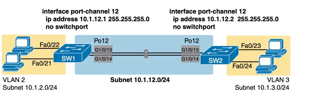
Example 17-12 Layer 3 EtherChannel Configuration on Switch SW1 (Odom, 2020, p. 465)
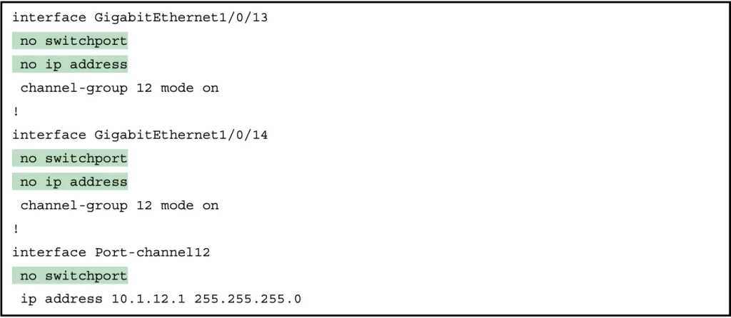
As we saw in the previous section, the IP address should be configured on the PortChannel interface only, not the physical interface.
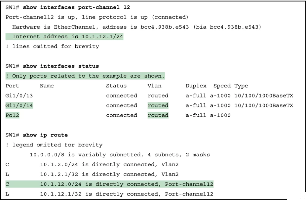
Once configured, the PortChannel interface appears in several show commands (see Example 17-13). The commands that list IP addresses and routes refer to the PortChannel interface.
Example 17-13 Verification Commands Listing Interface Port-Channel 12 from Switch SW1 (Odom, 2020, p. 466)
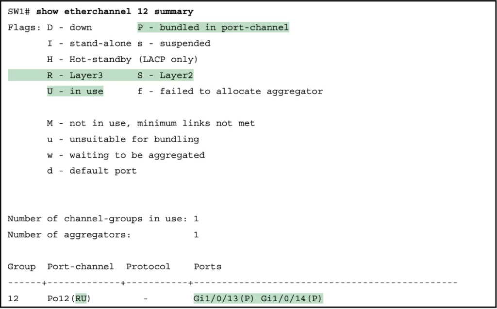
For further verification, you can examine the EtherChannel directly with the show etherchannel summary command as listed in Example 17-14.
Example 17-14 Verifying the EtherChannel (Odom, 2020, p. 467)
Configuration/verification command review
>EtherChannel load-balancing verification and configuration:
ASW#show etherchannel load-balance
ASW(config)#port-channel load-balance method
>Configuring dynamic L2 EtherChannels (PAgP and LACP):
Interface commands (create “port channels” virtual interfaces):
channel-group channel-group-number mode {desirable | auto}
→to enable PAgP on a port channel (virtual interface) = channel group-number
channel-group channel-group-number mode {active | passive}
→to enable LACP on a port channel (virtual interface) = channel group-number
desirable + desirable or auto
active + active or passive
Example:
ASW1(config)#interface range g0/0 – 3
ASW1(config-if-range)#channel-group 1 mode desirable
→to enable PAgP on port channel 1. The command will create the port-channel interface
You can check for the configured interface with show ip interface brief.
>Configuring manual (static) L2 EtherChannels:
channel-group channel-group-number mode on
show etherchannel [channel-number] summary
→to verify the status of an EtherChannel
show etherchannel port-channel
→to see the number of ports in the port-channel and to see which protocol is being used; to see the channel-group mode for each port
>Manually configure negotiation protocol (PAgP or LACP):
Interface config mode:
channel-protocol {lacp | pagp}
After configuring the EtherChannel with a protocol, e.g., LACP, we can then configure the port-channel interface itself.
Let’s use LACP as an example.
>Configure the port-channel 1 interface as a trunk from interface configuration mode (example):
ASW1(config)#interface port-channel 1
→to enter PortChannel configuration mode and to create the PortChannel if not already created
ASW1(config-if)#switchport trunk encapsulation dot1q
ASW1(config-if)#switchport mode trunk
show interfaces trunk
→to confirm port-channel 1 (Po1) has been configured as a trunk
>Configure a dynamic L3 EtherChannel (example):
ASW1(config)#interface range g0/0 – 3
→to enter interface range config mode for the member interfaces
ASW1(config-if-range)#no switchport
→to set the interfaces as L3 routed interfaces
ASW1(config-if-range)#channel-group 1 mode active
→to enable LACP
ASW1#show running-config
→to check the configuration on port channel 1 (po1)
To assign an IP address to a port channel (po1):
#interface port-channel 1
#ip address 10.0.0.1 255.255.255.252
>Configure a static L3 Etherchannel (example):
interface range g0/0 – 3
no switchport
channel-group 1 mode on
interface po1
ip address 10.1.12.1 255.255.255.0
show interfaces po1
show interfaces status
show ip route
show etherchannel 1 summary
>The show commands in one syntax:
SW#show etherchannel [channel-group number] {brief | detail | port | port-channel | summary}
→to display information about the state of EtherChannels
Free CCNA | Configuring EtherChannel | Day 23 Lab – Notes
Practice quiz questions
Quiz question 1
Which of the following channel-group mode combinations will result in an operational EtherChannel? Choose three.
A, on – on
B, passive – passive
C, desirable – auto
D, auto – auto
E, active – desirable
F, on – desirable
G, active – active
The answers are A, C, and G.
You can find two more practice questions for this lesson (plus a bonus one) in Jeremy’s EtherChannel video, cited below.
You can find four quiz questions and answers on Layer 2 EtherChannel configuration in Odom, 2020, pp. 294-296.
You can find two quiz questions and answers on Layer 3 EtherChannel configuration in Odom, 2020, pp. 448-450.
Key references
Free CCNA | EtherChannel | Day 23 | CCNA 200-301 Complete Course
Free CCNA | Configuring EtherChannel | Day 23 Lab | CCNA 200-301 Complete Course
Odom, W. (2020). Chapter 10. RSTP and EtherChannel Configuration, CCNA 200-301 Official Cert Guide (pp. 292-313), Volume 1. Cisco Press.
Odom, W. (2020). Chapter 17. IP Routing in the LAN, CCNA 200-301 Official Cert Guide (pp. 446-470), Volume 1. Cisco Press.
Related content
Classic Spanning Tree port states
Compliance frameworks and industry standards
How data flow through the Internet
How to break into information security
IT career paths – everything you need to know
Job roles in IT and cybersecurity
Network security risk mitigation best practices
STP root bridge election and root port selection
The GRC approach to managing cybersecurity
The penetration testing process
The Security Operations Center (SOC) career path
Back to DTI Courses


