STP (Spanning Tree Protocol) is an important topic for network engineers to understand and for the CCNA. This post represents Part 1 of 3 of STP study notes for the CCNA. This lesson, STP root bridge election and root port selection, introduces classic STP and discusses its role in regulating traffic flow within Ethernet segments. A resilient network is designed with redundant pathways to ensure continuity in the case of a connection or port failure. STP topology provides network redundancy while preventing network loops from forming and crippling the network. This lesson covers the steps of Spanning Tree’s process of creating loop-free Layer 2 LANs.
STP Part 2, Classic Spanning Tree port states, focuses on classic STP port states (blocking, listening, learning, and forwarding), STP timers (hello, forward delay, and max age), STP Toolkit (PortFast and BPDU Guard), and STP configurations (mode, root bridge, and root cost and port priority).
STP Part 3, Basic operations of Rapid PVST+ STP, focuses on RSTP port states (discarding, learning, and forwarding), RSTP port roles (alternate and backup), STP optional features built into RSTP (UplinkFast, BackboneFast, and PortFast), RSTP configuration in CLI, and RSTP link types (edge, point-to-point, and shared). This post represents Issue 15 of my CCNA 200-301 study notes.
- Redundancy in networks – why it is important
- Layer 2 loops (broadcast storms)
- The role of classic STP in regulating traffic flow within Ethernet segments
- Introduction to STP
- STP demonstration
- STP process
- Root bridge election
- Root bridge election demo
- PVST+, extended system ID
- Root bridge (cont.)
- Classic STP port roles
- Root port selection via root cost
- Root cost
- Root port selection via neighbor Bridge ID
- Identify root bridge, root ports
- Root port selection via neighbor port ID
- Blocking ports to prevent loops
- Key references
You may also be interested in CCNA 200-301 study notes.
Redundancy in networks – why it is important
Redundancy is an essential part of network design. Modern networks are expected to run 24/7/365. Even a short downtime can be disastrous for a business.
Redundancy must be implemented at every possible point in a network. If one network component fails, other components should be able to step in and take over the functions of the failed components to ensure the system experiences little or no downtime.
Network engineers are responsible for business-critical infrastructure and they must ensure that the network infrastructure is resilient to failures as much as possible.
Here is an example of a poorly designed network. There are many potential points of failure which could disconnect the network.
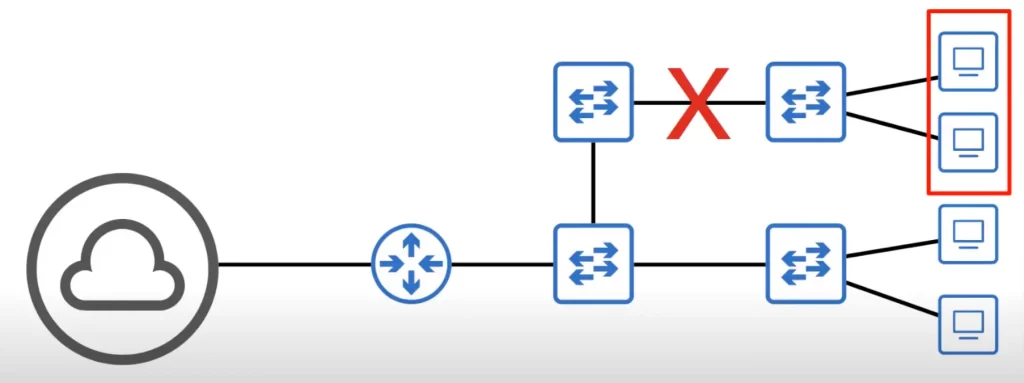
For example, if the connection between the router and the Internet is cut due to a hardware failure, this entire network loses connectivity to the Internet. If the connection marked by a red X is cut off due to a hardware failure, the hosts in the red box lose connectivity within the LAN, and out to the Internet.
Here’s a better network design.
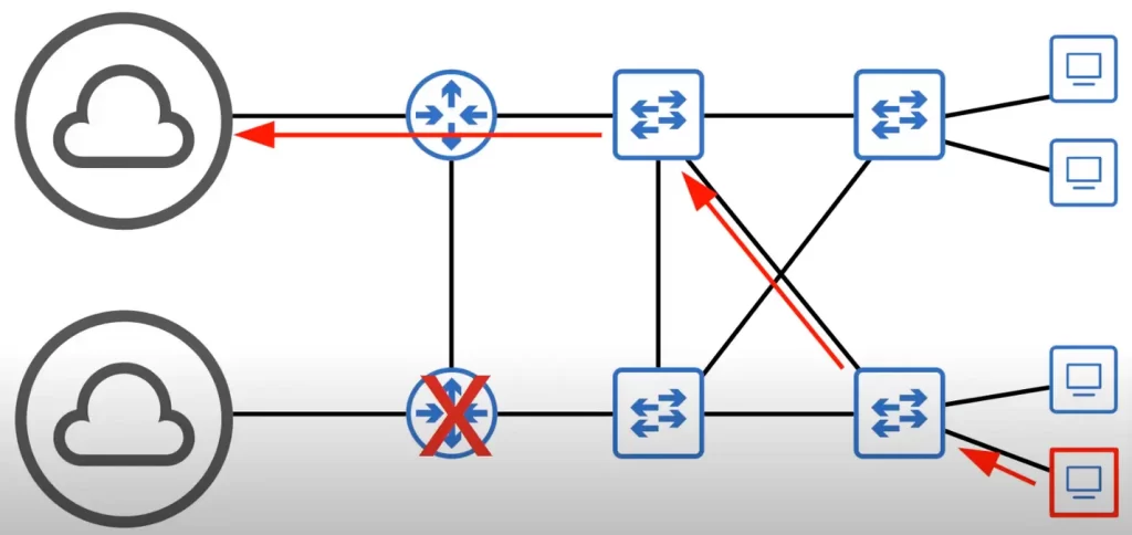
For example, if the PC in the red box wants to reach the Internet, it might use the lower path in a normal situation; however, if the router (marked with a red X) in the lower path has a hardware failure and goes down, the PC can reach the Internet via another alternative path (shown with the red arrows).
Layer 2 loops (broadcast storms)
Spanning Tree enables redundant Layer 2 networks. We saw how a redundant LAN can be beneficial. Having multiple paths between switches provides alternate paths if one connection fails.
But there’s a catch. A network with redundant paths can result in Layer 2 loops.
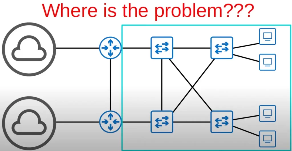
Consider this network layout. It screams out, “I want my Spanning Tree!” There is a problem that can cripple the network. A broadcast storm can form.
Let’s use a simplified network topology to illustrate the concept of broadcast storms.
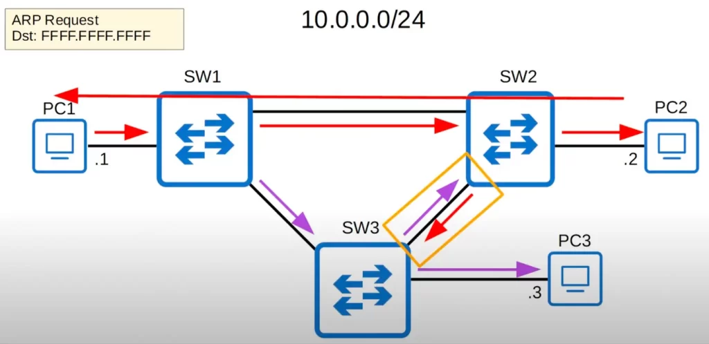
PC1 is 10.0.0.1, PC2 is 10.0.0.2, and PC3 is 10.0.0.3. PC1 wants to send some traffic to PC2. To do that, it needs to know PC2’s MAC address. So PC1 sends an ARP request, which is a broadcast frame that uses the broadcast MAC address of all F’s as its Layer2 address. When SW1 receives the broadcast frame, SW1 will flood the frame out of all interfaces, except the one it was received on. Recall, a switch will flood broadcast and unknown unicast frames. SW2 and SW3 both receive a copy of the frame. SW2 and SW3 will then flood the frame out all interfaces except the one it was received on. PC2 receives the ARP request and will reply with a unicast ARP reply.
So where is the problem?
Although PC2 received the ARP request and sent its reply, broadcast frames remain on the network (notice the yellow rectangle between SW3 and SW2). The switches will keep flooding the frames. SW1 might receive two broadcast frames on two different interfaces, and again flood them. Similarly, SW2 and SW3 may also keep receiving and flooding broadcast frames in an infinite loop type scenario.
If enough of these looped broadcasts accumulate in the network, the network will be too congested for legitimate traffic to use the network. This is called a broadcast storm.
The IP header has the TTL or Time To Live field, used to prevent infinite loops at Layer 3. The Ethernet header does not have a TTL field.
Eventually the network will be full of looping broadcast frames such that no regular traffic can pass through the network.
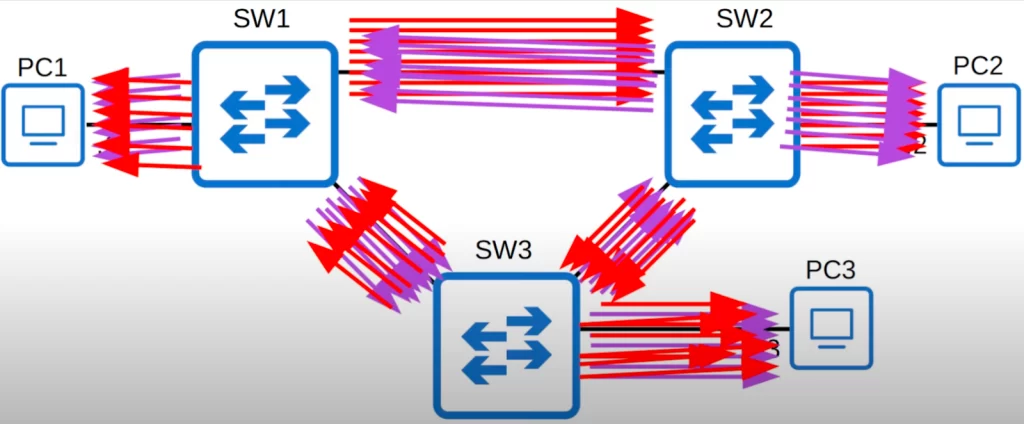
The red arrows represent the clockwise loop between the three switches and the purple arrows represent the counter-clockwise loop.
Network congestion is not the only problem. Each time a frame arrives on a switchport, the switch uses the source MAC address field to learn the MAC address and update its MAC address table. When the frames with the same source MAC address repeatedly arrive on different interfaces, the switch is continuously updating the interface in its MAC address table. This is known as MAC Address Flapping.
So how can we design a network with redundant paths that does not result in Layer 2 loops?
There are a few ways.
One way is to use a Spanning Tree protocol (STP). STP works by electing a root bridge for the network and then building a Spanning Tree that includes all of the switches in the network. The Spanning Tree includes only one path between any two devices in the network. If a link fails, STP will automatically recalculate the Spanning Tree and open a new path.
Another way is to use a link aggregation control protocol (LACP). LACP is a Layer 2 protocol that allows you to group multiple physical links together to create a single logical link. LACP works by negotiating between two switches to agree on which links should be grouped together. Once the links are grouped together, they appear to the network as a single logical link. This allows you to have redundant paths between devices without the risk of Layer 2 loops.
Overall, STP is a more mature and widely supported protocol than LACP. However, LACP can provide better performance and bandwidth than STP. If you need to prevent Layer 2 loops in a network with a variety of topologies, STP is a good choice. If you need to improve bandwidth and performance between two switches, LACP is a better option.
Finally, you can also design your network to avoid Layer 2 loops by using physical separation. This means that you should not connect devices from different segments of your network to the same switch. If you do this, you could create a Layer 2 loop even if you are not using STP or LACP.
Here are some additional considerations when designing a network with redundant paths:
- The type of traffic that will be flowing through the network. For example, if you have mission-critical traffic, you may want to use a more sophisticated redundancy solution than if you are just transferring files.
- The size of the network. A larger network will require more redundancy than a smaller network.
- The budget. Redundancy can add to the cost of a network, so you need to make sure that you are getting the right amount of redundancy for your needs.
The role of classic STP in regulating traffic flow within Ethernet segments
A network loop occurs when there are two or more redundant paths between two network devices. This can cause broadcast storms, which can flood the network with unnecessary traffic and bring the network to a halt. STP prevents Layer 2 loops by blocking redundant paths.
Switches use BPDUs (Bridge Protocol Data Units) to communicate with each other and to build the Spanning Tree.
Classic STP works by electing a root bridge, which is the central point of the network.
Once the network topology has converged and all switches agree on the root bridge, only the root bridge sends BPDUs. The reason all switches send BPDUs at first is because they all think they are the root bridge.
STP still uses the term bridge, though bridges are not used much in modern networks. When we use the term bridge in our present discussion on STP, we really mean switch.
Classic STP prevents network loops within LANs by blocking ports that are not necessary for traffic flow. This ensures that there is only one path between any two network devices, which prevents broadcast storms from occurring.
Each link between two switches is a separate collision domain (Ethernet segment). Every collision domain has a single Spanning Tree designated port. Designated ports are in a forwarding state. The switch forming a connection (link) with the switch with the designated port will make its port non-designated (blocking). Blocked ports do not forward traffic, which prevents network loops from forming.
STP is a simple and effective way to prevent network loops in switched networks. However, it can have some drawbacks/limitations, such as:
- Slow convergence time: Classic STP can take several minutes to converge after a topology change. This can cause disruption to network traffic.
- Not scalable: Classic STP can become inefficient in large networks with a large number of switches and links.
- Not resilient to link failures: If a link fails, Classic STP can take several minutes to re-calculate the Spanning Tree and open a new path. This can cause disruption to network traffic.
To address these limitations, newer STP protocols have been developed, such as Rapid STP (RSTP) and Multiple Spanning Tree Protocol (MSTP). These protocols offer faster convergence time, better scalability, and more resilience to link failures.
Here are some of the advantages of RSTP over Classic STP:
- Faster convergence time: RSTP converges in a few seconds, as opposed to several minutes for Classic STP.
- More efficient: RSTP uses a shorter Spanning Tree, which can improve network performance.
- More resilient to link failures: RSTP can re-calculate the Spanning Tree and open a new path more quickly if a link fails.
Here are some of the advantages of MSTP over Classic STP:
- Supports multiple topologies: MSTP can support multiple topologies in a single network, which can improve network scalability.
- More efficient: MSTP uses a shorter Spanning Tree than Classic STP, which can improve network performance.
- More resilient to link failures: MSTP can re-calculate the Spanning Tree and open a new path more quickly if a link fails.
Introduction to STP
*Switches from all vendors run STP by default. Classic STP is IEEE 802.1D. This is the type of STP we will focus on in STP Part 1.
*STP prevents Layer 2 loops by placing redundant ports in a blocking state, essentially disabling the interface. Interfaces in a blocking state act as backups that can enter a forwarding state if an active interface (an interface that is currently forwarding) fails.
*Interfaces in a forwarding state behave normally. They send and receive all normal traffic. However, interfaces in a blocking state only receive STP messages called BPDUs, beside some other specific traffic.
Here are some of the specific traffic that interfaces in a blocking state may receive:
- Management traffic: This traffic is used to manage the switch, such as configuring the switch or viewing the switch’s status.
- LLDP: Link Layer Discovery Protocol is a protocol that allows switches to discover each other and exchange information about their links.
- CDP: Cisco Discovery Protocol is a Cisco proprietary protocol that allows Cisco switches to discover each other and exchange information about their links.
In addition to BPDUs and these specific types of traffic, interfaces in a blocking state may also receive some other types of traffic, such as:
- Broadcast traffic: This traffic is sent to all devices on the network.
- Multicast traffic: This traffic is sent to a group of devices on the network.
However, this traffic is typically dropped by the switch before it reaches the interface in the blocking state. This is because the switch does not have a path to forward the traffic to the destination device.
*STP-enabled switches send Hello BPDUs out of all ports (except blocking ports) once every 2 seconds.
If a switch receives a Hello BPDU on an interface, it knows the interface is connected to another switch. Routers, PCs, servers, and wireless APs typically do not use STP, they do not send Hello BPDUs.
STP demonstration
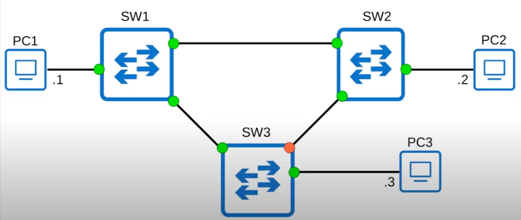
If we look at this topology again, these green-lit interfaces are in a forwarding state, while the one orange-lit interface on SW3 is in a blocking state, effectively disabling the connection between SW2 and SW3.
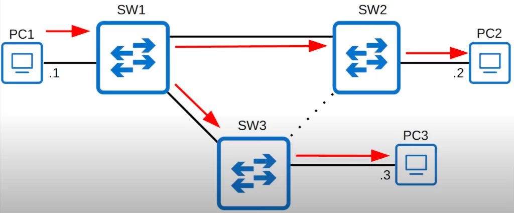
If PC1 sends an ARP request (a broadcast frame), it will be flooded as follows. No loops.
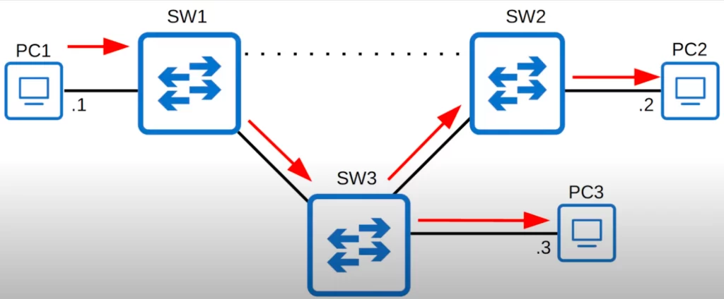
If at some point another interface fails, say the interface on SW2 receiving traffic from SW1, the switches will automatically adjust the topology and the broadcast frame would be flooded as follows. Again, no loops.
*By selecting which ports are forwarding and which ports are blocking, STP creates a single path to and from each point in the network. This prevents Layer 2 loops.
*There is a set process that STP uses to determine which ports should be forwarding and which should be blocking.
That process is what we will cover next.
STP process
Here is a summary of the process of selecting the different port roles and states in a Spanning Tree network.
When the switches first come up, they start the root switch election process. Each switch transmits a BPDU to the directly connected switch on a per-VLAN basis.
1. One switch per VLAN is elected as the root bridge, the switch with the lowest Bridge ID. All ports on the root bridge are designated ports (in a forwarding state).
As the BPDU goes out through the network, each switch compares the BPDU that the switch sends to the BPDU that the switch receives from the neighbors. The switches then agree on which switch is the root switch. The switch with the lowest Bridge ID in the network wins this election process.
2. Each remaining switch selects one of its interfaces to be a root port.
Each switch determines the best path to get to the root. The switches determine this path by a comparison of the information in all the BPDUs that the switches receive on all ports. The switch uses the port with the least amount of information in the BPDU in order to get to the root switch; the port with the least amount of information in the BPDU is the root port.
2.1. The interface with the lowest root cost is selected. If that’s a tie,
2.2. The interface connecting to a neighboring switch with the lowest Bridge ID is selected. If that’s a tie also,
2.3. The interface connected to the lowest port ID on the neighbor switch is selected.
The root port must be set to forwarding mode.
Ports across from the root port are always designated ports.
3. Each remaining collision domain will select one interface to be a designated port (in a forwarding state), and the other port will be non-designated (the switch forming a connection with the switch with the designated port will make its port non-designated, in a blocking state). The interface on the switch with the lowest root cost will be designated. If that’s a tie, the interface on the switch with the lowest Bridge ID will be designated.
The switches on each LAN segment communicate with each other to determine which switch is best to use in order to move data from that segment to the root bridge. This switch is called the designated switch.
Root bridge election
Back to our topology. These switches will send BPDUs out of each interface (follow the green arrows). The switches use these BPDUs to advertise themselves to other switches and to learn about other switches.
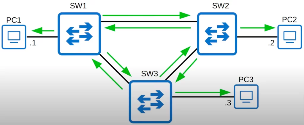
What exactly are these BPDUs used for?
*Switches use the Bridge ID field in the STP BPDU to elect a root bridge for the network.
*The switch with the lowest Bridge ID becomes the root bridge.
Traditionally, the Bridge ID field of the Spanning Tree BPDU looked like this. There is a Bridge Priority field, 16 bits in length, and there is the MAC address of the switch, 48 bits in length.
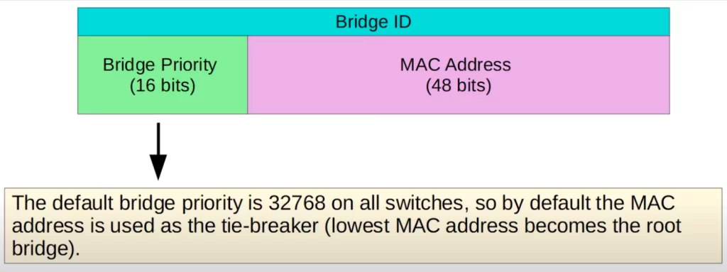
The default Bridge Priority is 32768 on all switches, so by default the MAC address is used as the tiebreaker. The switch with the lowest MAC address becomes the root bridge. The Bridge Priority is compared first, if there is a tie the MAC address is then compared.
Root bridge election demo
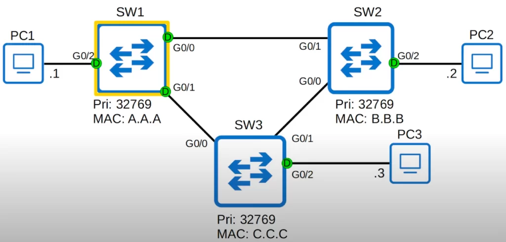
Here’s that topology again.
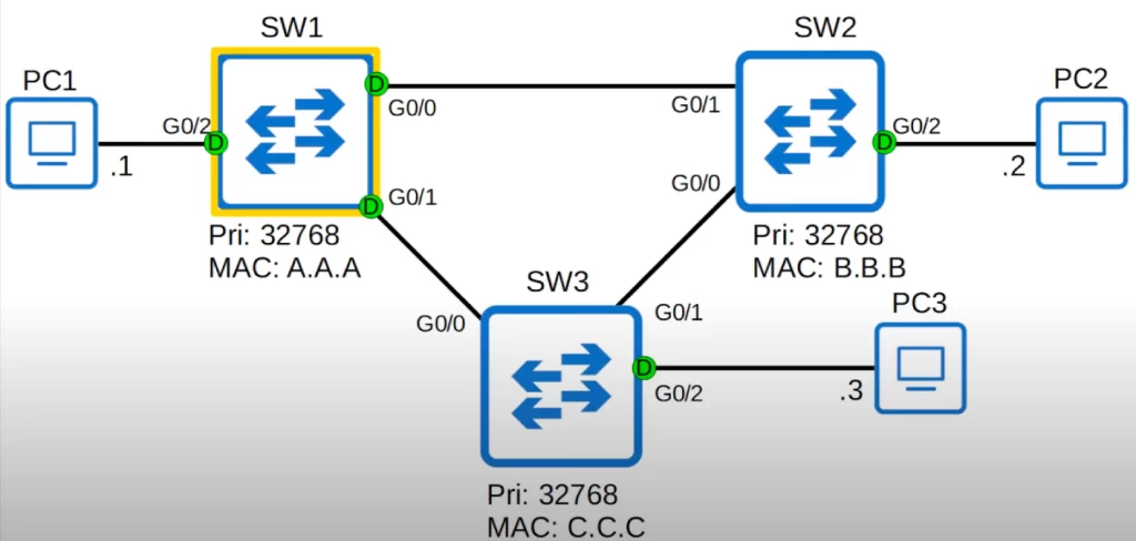
The priority (Bridge Priority) and MAC address for each switch are given. MAC addresses are shortened to three characters for convenience (they are actually 12 hexadecimal digits). Green-lit Interfaces are forwarding.
The G0/2 interface on each switch is connected to a PC. Because the G0/2 interface on each switch is not receiving any BPDUs, the switch knows it is safe to go into forwarding mode. There is no risk of creating a Layer 2 loop, so these port lights are all green.
All three switches have the default priority of 32768. To know which switch will be the root bridge we compare the MAC addresses. The lowest Bridge ID wins.
SW1 has the lowest MAC address. Therefore, SW1 becomes the root bridge of this network (hexadecimal A is equal to 10, B is equal to 11, and C is equal to 12).
All ports on the root bridge become designated ports, in a forwarding state.
PVST+, extended system ID
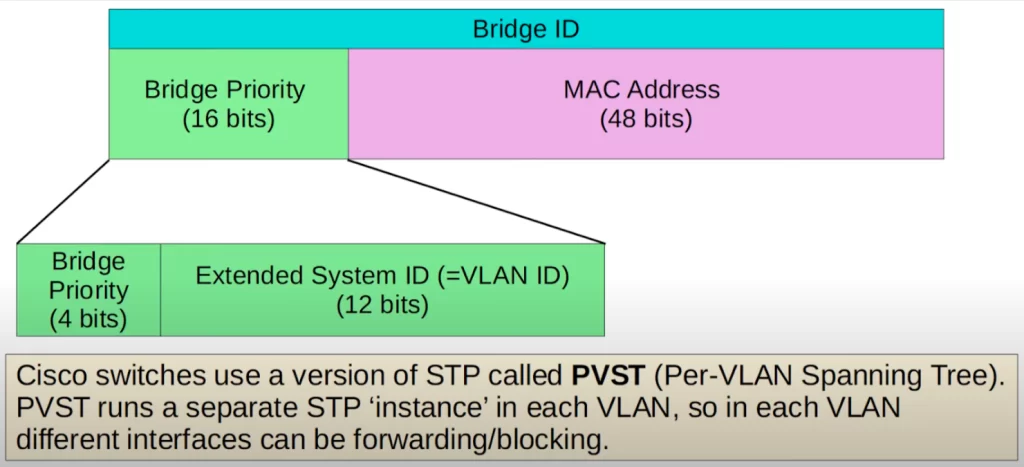
The Bridge ID we saw earlier was the traditional Bridge ID. However, the Bridge ID has been updated to look like this.
The Bridge Priority (16 bits) has been updated to be made of two parts, the bridge priority field (4 bits), and the extended system ID field (12 bits), which is the VLAN ID.
Why include a VLAN ID in the Bridge Priority?
In classic STP, all VLANs share one STP instance. This means that all ports in the network are part of the same STP topology. When STP converges, it blocks all but one port between any two switches. This is done to prevent loops from forming in the network.
If we want to block different ports in each VLAN to achieve load balancing, we need to use a different STP mode. One option is to use PVST+ (Per VLAN Spanning Tree Protocol). PVST+ is a Cisco proprietary STP mode that allows for multiple STP instances to be configured in the same network.
PVST+ runs a separate STP instance in each VLAN. For example, if you have a network with 10 VLANs, you could have 10 STP instances running on each switch, one instance for each VLAN. In each VLAN different interfaces can be forwarding or blocking. One interface could be forwarding in VLAN1, but blocking in VLAN2, for example. This would allow you to have different root bridges and topologies for each VLAN, and you could also configure different ports in each VLAN to be used for different traffic flows.
By adding the VLAN ID into the Bridge Priority, the switch will have a different Bridge ID in each VLAN.
Here’s a closer look at the Bridge Priority field.
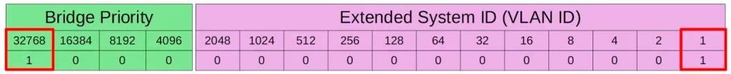
32768 is the default Bridge Priority because the Bridge Priority field is 16 bits in length (2^0 → 2^15), and the most significant bit in the field is set to 1 by default (2^15 = 32768).
However, with the addition of the extended system ID, the VLAN ID, this default value changed. The default VLAN ID is 1. Therefore the default Bridge Priority in total is 32769.
In the default VLAN of 1, the default Bridge Priority is 32769, which is 32768 + 1.
Ponder this: if you want to increase the switch’s Bridge Priority without changing VLAN numbers, what is the minimum unit of increase/decrease?
The bridge priority and extended system ID together are a single field in the Bridge ID, i.e., the Bridge Priority field. However, the extended system ID is set and cannot be changed because it is determined by the VLAN ID. Therefore, you can only change the total Bridge Priority (that is, the bridge priority + extended system ID) in units of 4096, the value of the least significant bit of the bridge priority portion.
The Bridge Priority is 32769. If we want to reduce it, just a little, on a switch to make the switch the root bridge, we can reduce it to 28673, which is 16384 plus 8192 plus 4096 plus 1 (or 32769 – 4096).
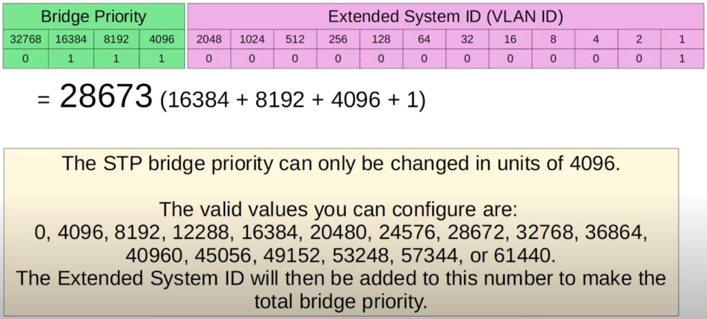
We could reduce the Bridge Priority more, but the point is this: the STP Bridge Priority can only be changed in units of 4096. The valid values you can configure are shown in the above diagram, starting from 0 and increasing in units of 4096.
Root bridge (cont.)
Some key points about the root bridge…
*When a switch is powered on, it assumes it is the root bridge. A switch will only give up its position if it receives a superior BPDU, meaning, a BPDU from a switch with a lower Bridge ID.
*Once the topology has converged and all switches agree on the root bridge, only the root bridge sends BPDUs. The reason all switches send BPDUs at first is because they all think they are the root bridge.
Other switches in the network will forward BPDUs from the root bridge, but they will not generate their own original BPDUs.
*STP puts ports in either a blocking or forwarding state to avoid Layer 2 loops in the network.
All ports on the root bridge are put in a forwarding state, and all other switches in the topology must have a path to reach the root bridge.
Let’s look at the topology again (the diagram below). We will be looking at the STP topology for a single VLAN, VLAN1, the default VLAN on a switch.
The priority Pri (the Bridge Priority) for each switch is 32769. But if there are multiple VLANs, say VLAN1, VLAN2, and VLAN3 in this network, the priority would be 32770 for VLAN2, and 32771 for VLAN3, and so on.
So here in VLAN1, SW1 is the root bridge. All interfaces on the root bridge are designated ports. Designated ports are in a forwarding state.
Note, just FYI for now, we could also change the priority on the switches for a specific VLAN. For example, SW1 could be the root bridge in VLAN1, SW2 could be the root bridge in VLAN2, and SW3 could be the root bridge in VLAN3.
Classic STP port roles
*Root ports: ports on non-root switches (switches that are not the root bridge in a Spanning Tree network) with the best root cost to the root bridge. There can only be one root port per switch. These ports forward data to the root bridge.
*Designated ports: ports on root switches and designated switches. All ports on the root bridge will be designated. Ports across from (connected to) the root port are always designated ports.
*Non-designated/blocked ports: all other ports to switches are in a blocked state (access ports going to workstations or PCs are not affected). The non-designated port is a switch port that is blocked, so it is not forwarding data frames and not populating the MAC address table with source addresses.
Root port selection via root cost
So far we have covered the first step of Spanning Tree’s process of creating loop-free Layer 2 LANs: the switch with the lowest Bridge ID is elected as the root bridge. All ports on the root bridge are designated ports, so they are in a forwarding state.
The second step is: all other switches will select one of its ports to be its root port. That means there is one root port on each switch in the network. Root ports are also in a forwarding state.
The interface with the lowest root cost becomes the root port.
The root cost is the total cost of the outgoing interfaces along the path to the root bridge.
Root cost
Each interface has an associated Spanning Tree cost. Remember these path costs for the CCNA exam.
| Speed | STP cost |
| 10 Mbps (Ethernet) | 100 |
| 100 Mbps (Fast Ethernet) | 19 |
| 1 Gbps (Gigabit Ethernet) | 4 |
| 10 Gbps (Gigabit Ethernet) | 2 |
In our topology, we are using Gigabit Ethernet ports, so they all have a cost of 4. We count the cost of the sending, the outgoing interface, not the cost of the receiving interface. SW1 is the root bridge, so it has a cost of 0 on all interfaces. SW1 advertises its root cost of 0 in its BPDUs.
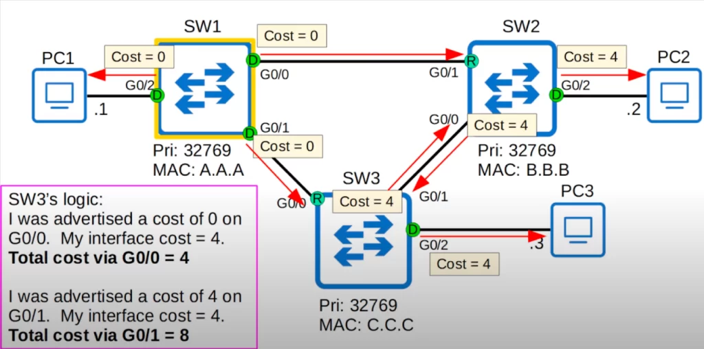
SW2 will choose G0/1 as its root port. Here is its logic. SW2 was advertised a cost of 0 on its G0/1 interface, however the cost of its interface is 4, therefore the total root cost via G0/1 is 4. SW2 was advertised a cost of 4 on G0/0, from SW3. However its interface also has a cost of 4, so the total root cost via G0/0 is 8. So SW2 will select G0/1 as the root port.
SW2 will receive the BPDU from SW1 and add the cost of its outgoing interface, G0/1, which is 4, when it floods those BPDUs out of its interfaces. SW3 will do the same.
SW3’s logic follows the same process. SW3 has a total cost of 4 via G0/0, and a total cost of 8 via G0/1, so it will select G0/0 as its root port.
In this case, the ports directly across from each root port are the root bridge, so they are already designated ports. Keep in mind that the port connected to another switch’s root port must be designated. Because the root port is the switch’s path to the root bridge, another switch must not block it.
Root port selection via neighbor Bridge ID
Let’s review the process of figuring out a Spanning Tree topology.
1. One switch is elected as the root bridge. All ports on the root bridge are designated ports (in a forwarding state). There is only one step in selecting the root bridge, that is, the switch with the lowest Bridge ID.
2. Each remaining switch will select one of its interfaces to be its root port (which is also in a forwarding state). Ports across from (connected to) the root port are always designated ports.
Criteria for root port selection:
2.1. The interface with the lowest root cost becomes the root port. If we need a tiebreaker, if a switch has multiple ports with the same root cost,
2.2. The interface connected to the neighbor switch with the lowest Bridge ID becomes the root port. If it’s a tie,
2.3. The interface connected to the lowest port ID on the neighbor switch becomes the root port.
Identify root bridge, root ports
Let’s identify the root bridge and root ports in a topology.
SW2 will become the root bridge because it has the lowest priority (Bridge Priority). So SW2’s ports are all designated.
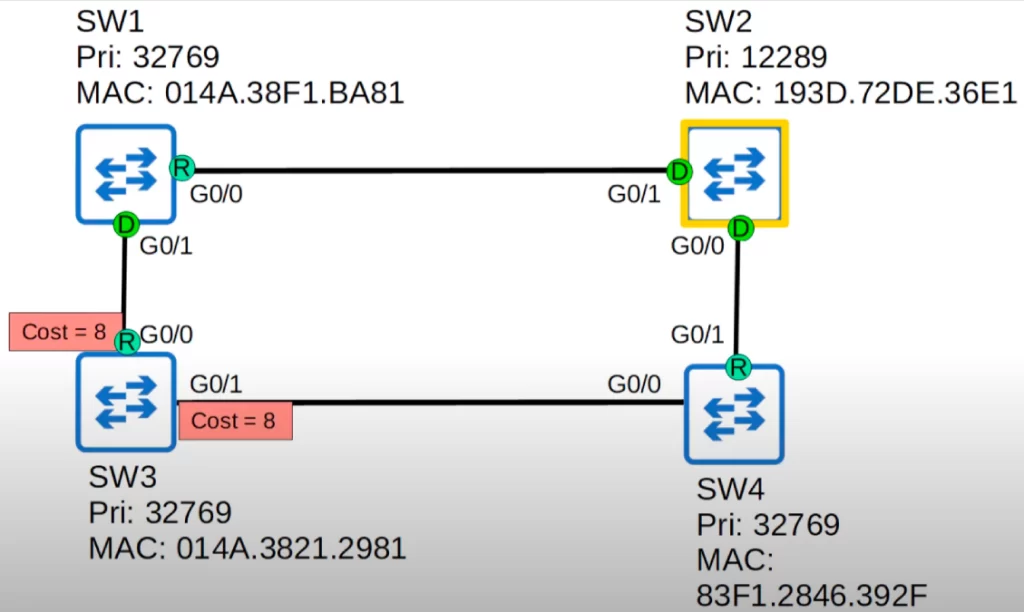
Which ports will become root ports? All interfaces are Gigabit Ethernet, so they all have a cost of 4. If there is a tie in root cost, the switch will select the interface connected to the neighbor with the lowest Bridge ID.
On SW1 and SW4, the answer is obvious, SW1’s G0/0 and SW4’s G0/1 have a cost of 4 each, so they are selected.
SW3 via G0/0 has a cost of 8 (4 plus 4); via G0/1 it has the same cost of 8 (4 plus 4). So we have to use the tiebreaker: which neighbor switch has the lowest Bridge ID, SW1 or SW4? It’s SW1, the priorities are the same, but SW1’s MAC address is lower. So SW3’s G0/0 is selected as the root port, and SW1’s G0/1 becomes designated.
Root port selection via neighbor port ID
There is one more tiebreaker that might be needed to select the root port: lowest neighbor port ID.
What if two switches have two connections between them, so both the root cost and the neighbor Bridge ID are the same? Then we get to the final tiebreaker: the interface connected to the interface on the neighbor switch with the lowest port ID will become the root port.
Here is the output of the command show spanning-tree. The command output lists the Spanning Tree port ID of each interface on the switch.
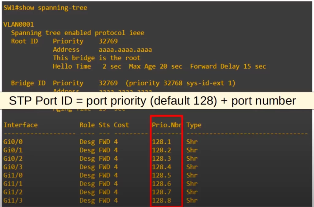
Note the column titled Prio.Nbr (Prio dot number) which is the STP port ID. Each port has a default priority of 128, and then a unique port number, 1 for G0/0, 2 for G0/1, etc. on this switch. The STP port ID equals the port priority plus the port number. Similar to the Bridge ID, where the MAC address is used as a tiebreaker if the priorities tie, in this case the port number is used as a tiebreaker if the priorities tie.
Let’s look at an example: identify the root port
SW2 is still the root bridge, but now there are two connections between SW1 and SW3. Which port will SW3 select as the root port? First, the root cost is the same for both interfaces, 8. Second, which interface is connected to the neighbor with the lowest Bridge ID? Again, the same for both interfaces. Third, which interface is connected to the lower port ID on the neighbor switch? SW3’s G0/2 interface.
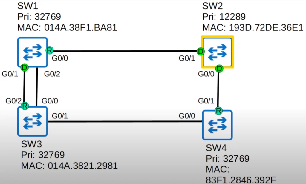
SW3’s G0/2 interface will become the root port, because it is connected to a lower port ID on the neighbor switch – SW1’s G0/1 interface has a lower port ID than its (SW1’s) G0/2 interface.
SW1’s G0/1 interface is a designated port, because it is connected to SW3’s root port.
Blocking ports to prevent loops
So far we have covered two key steps of Spanning Tree’s process of creating loop-free Layer 2 LANs: 1) switches elect a root bridge, and 2) switches each select one of its ports to be its root port.
Our process is not yet complete. We need to block some ports to prevent Layer 2 loops.
So let’s look at the third key step: each remaining collision domain selects one designated port and one non-designated port.
All that’s left is the connection between SW2 and SW3. Notice the red rectangle representing the connection between SW2’s G0/0 and SW3’s G0/1 that needs a blocked port to prevent loops.
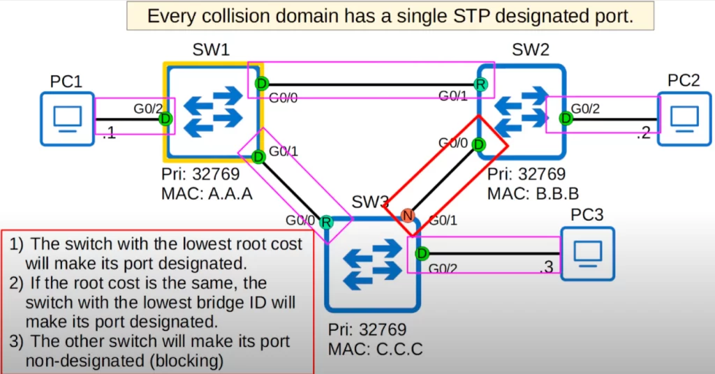
Each link between two switches is a separate collision domain. Every collision domain (Ethernet segment) has a single Spanning Tree designated port. The collision domain between SW1 and SW2 has one designated port, SW1’s G0/0. The connection between SW1 and SW3 has one designated port, SW1’s G0/1.
The connections with the PCs are all designated ports in the forwarding state, because the PCs do not participate in Spanning Tree.
We need one designated port on the connection between SW2 and SW3.
How do we determine which port will be designated, in a forwarding state? The switch with the lowest root cost will make its port designated. However, in this case both switches have the same root cost, 4 for SW2 via its G0/1 interface and 4 for SW3 via its G0/0 interface.
For the tiebreaker we compare the Bridge ID. SW2 has the lower Bridge ID, so its G0/0 interface will be designated. Finally, the other switch will make its port non-designated, which means it is in a blocking state, it blocks the port to prevent Layer 2 loops. SW3’s G0/1 is non-designated.
Free CCNA | Analyzing STP | Day 20 Lab – Notes
Key references
Note: The resources cited below (in the “Key references” section of this document) are the main source of knowledge for these study notes/this lesson, unless stated otherwise.
Free CCNA | Spanning Tree Protocol (Part 1) | Day 20 | CCNA 200-301 Complete Course
Free CCNA | Analyzing STP | Day 20 Lab | CCNA 200-301 Complete Course
Other references/resources
Spanning Tree Protocol (STP) Overview. (2021). Port and VLAN Configuration. Cisco Systems, Inc.
Related content
Basic operations of Rapid PVST+ STP
Classic Spanning Tree port states
Compliance frameworks and industry standards
How data flow through the Internet
How to break into information security
IT career paths – everything you need to know
Job roles in IT and cybersecurity
Network security risk mitigation best practices
The GRC approach to managing cybersecurity
The penetration testing process
The Security Operations Center (SOC) career path
Back to DTI Courses


