This post represents Part 2 of 3 of STP study notes for the CCNA. This lesson, Classic Spanning Tree port states, continues to explore the operation of Spanning Tree. More specifically, this lesson focuses on classic Spanning Tree port states (blocking, listening, learning, and forwarding), STP timers (hello, forward delay, and max age), STP Toolkit (PortFast and BPDU Guard), and STP configurations (mode, root bridge, and root cost and port priority).
STP Part 1, STP root bridge election and root port selection, introduced classic STP and discussed its role in regulating traffic flow within Ethernet segments. A resilient network is designed with redundant pathways to ensure continuity in the case of a connection or port failure. STP topology provides network redundancy while preventing network loops from forming and crippling the network. STP Part 1 covered the steps of Spanning Tree’s process of creating loop-free Layer 2 LANs.
STP Part 3, Basic operations of Rapid PVST+ STP, focuses on RSTP port states (discarding, learning, and forwarding), RSTP port roles (alternate and backup), STP optional features built into RSTP (UplinkFast, BackboneFast, and PortFast), RSTP configuration in CLI, and RSTP link types (edge, point-to-point, and shared). This post represents Issue 16 of my CCNA 200-301 study notes.
- Classic Spanning Tree port states
- The blocking state
- The listening state
- The learning state
- The forwarding state
- STP port states chart
- Spanning Tree timers
- The hello timer
- The forward delay timer
- The max age timer
- STP BPDU (Bridge Protocol Data Unit)
- STP optional features (STP Toolkit)
- STP Toolkit PortFast
- STP Toolkit BPDU Guard
- STP Toolkit Root Guard/Loop Guard
- STP configuration – mode (MST, PVST+, Rapid PVST+)
- STP configuration – root bridge
- STP load balancing
- Configuring STP port settings
- Command review
- Key learnings
- Key references
You may also be interested in CCNA 200-301 study notes.
Classic Spanning Tree port states
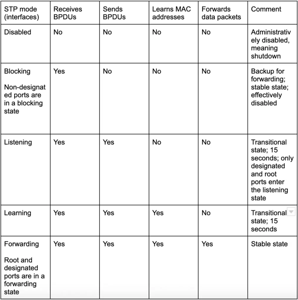
STP Part 1 looked at the forwarding and blocking STP port states. There are a couple of other transitional states between those two, listening and learning, and some timers that determine when the switch moves between each state.
Forwarding and blocking are stable states. Listening and learning are transitional states.
*Root ports and designated ports remain stable in a forwarding state, and non-designated ports remain stable in a blocking state.
*Root and designated ports only remain stable as long as there are no changes in the network topology. If a new device is added, an interface is shutdown, or a hardware failure occurs in the topology, ports may have to change states.
*Listening and learning are transitional states which are passed through when an interface is activated or when a blocking port must transition to a forwarding state due to a change in the network topology.
*The disabled state refers to an interface that is administratively disabled, meaning shutdown.
STP port states interface modes
The blocking state
*Non-designated ports are in a blocking state.
*Interfaces in a blocking state are effectively disabled to prevent loops. Disabling redundant interfaces prevents loops.
*Interfaces in a blocking state do not send/receive regular network traffic. Regular traffic arriving on an interface in a blocking state is dropped.
*However, interfaces in a blocking state receive STP BPDUs. Interfaces in a blocking state need to receive and process BPDUs to participate in the Spanning Tree topology and be ready to transition to a forwarding state if they need to.
*Interfaces in a blocking state do not forward STP BPDUs.
*Interfaces in a blocking state do not learn MAC addresses. If regular traffic arrives on the interface it is dropped.
The listening state
*After the blocking state, interfaces with a designated or root role enter the listening state. In the listening state a switch port does not forward traffic, but does listen for BPDUs. This allows the switch to learn about the topology of the network before it begins forwarding traffic.
*Only designated and root ports enter the listening state. Non-designated ports are always blocking. There is no need for a non-designated port to enter the listening state because the listening state is a transitional state that eventually leads to a forwarding state.
*The listening state is 15 seconds long by default. The length of the listening state is determined by a timer called the forward delay timer. The default value of the forward delay timer is 15 seconds.
*An interface in the listening state only forwards/receives Spanning Tree BPDUs.
*An interface in the listening state does not send or receive regular traffic. If a port in the listening state receives a regular unicast frame, the switch will discard the frame.
*An interface in the listening state also does not learn MAC addresses from regular traffic that arrives on the interface.
When a frame arrives on a switch interface, the switch uses the frame’s source MAC address field to learn about that MAC address. The switch updates its MAC address table with the MAC address, interface, and VLAN information. If an interface is in the STP listening state, this does not happen. Traffic is simply dropped.
The learning state
*After the listening state, a designated or root port will enter the learning state.
*The default length of the learning state is 15 seconds. This default time is determined by the forward delay timer (the same timer is used for both the listening and learning states), so by default it takes a total of 30 seconds to move through both states and enter a forwarding state.
*As in the listening state, an interface in the learning state only sends or receives STP BPDUs. An interface in the learning state does not send or receive regular traffic.
*However, an interface in the learning state learns MAC addresses from regular traffic that arrives on the interface. An interface in the learning state builds up some of its MAC address table in preparation for the forwarding state.
The forwarding state
*Root and designated ports are in a forwarding state when they are stable.
*A port in the forwarding state operates as normal. Meaning, the port 1) sends and receives BPDUs, 2) sends and receives normal traffic, and 3) learns MAC addresses from the frames that arrive on it, and adds them to the MAC address table. It is a switch port operating as normal.
STP port states chart
Here is another summary of each STP port state.
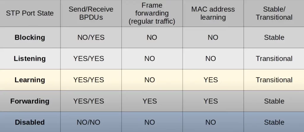
Try to remember these states, which states send and receive BPDUs, which states forward traffic, which states learn MAC addresses, and which states are stable and which states are transitional.
Spanning Tree timers
Now we discuss the timers used in Spanning Tree – hello, forward delay, and max age timers.
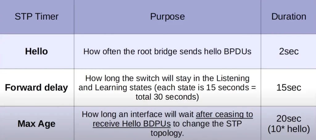
First up, the hello timer.
The hello timer is a setting on the root bridge that determines how often the root bridge sends hello BPDUs. By default, the hello timer is set to 2 seconds. This means that the root bridge will send a hello BPDU every 2 seconds.
Other switches in the network do not originate their own BPDUs, but they will forward BPDUs they receive. However, switches will only forward BPDUs on their designated ports.
Let’s see how that works.
Assuming these switches all come online at the same time, each switch will assume it is the root bridge, and each switch will send BPDUs out of all interfaces.
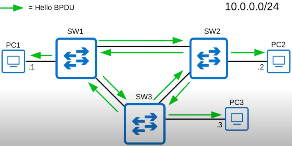
However, once the network has converged and all switches and ports are stabilized in their roles, only the root bridge sends BPDUs.
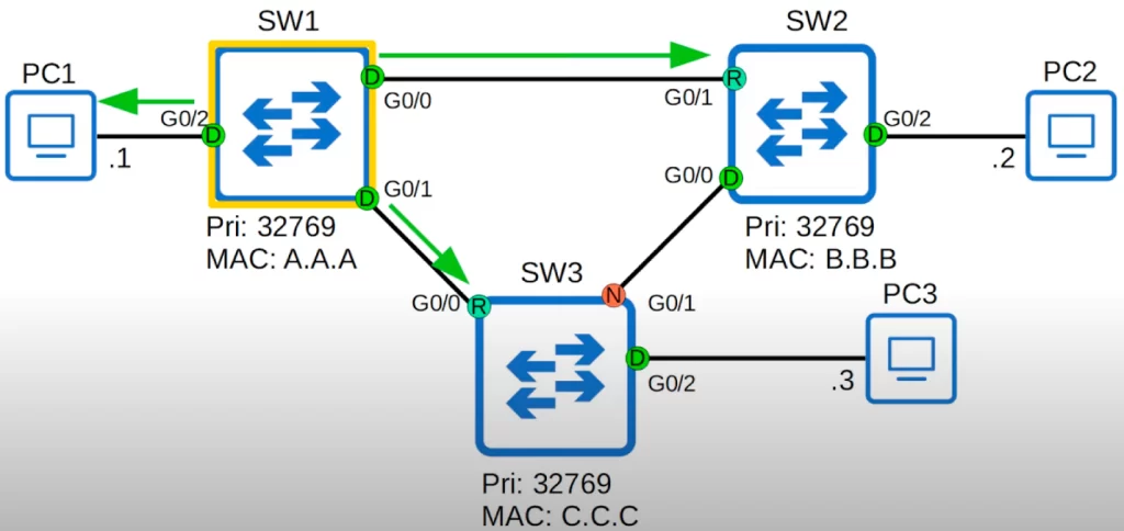
Then, the other switches will forward these BPDUs on their designated ports, updating information like the bridge root cost, Bridge ID, port ID, etc.
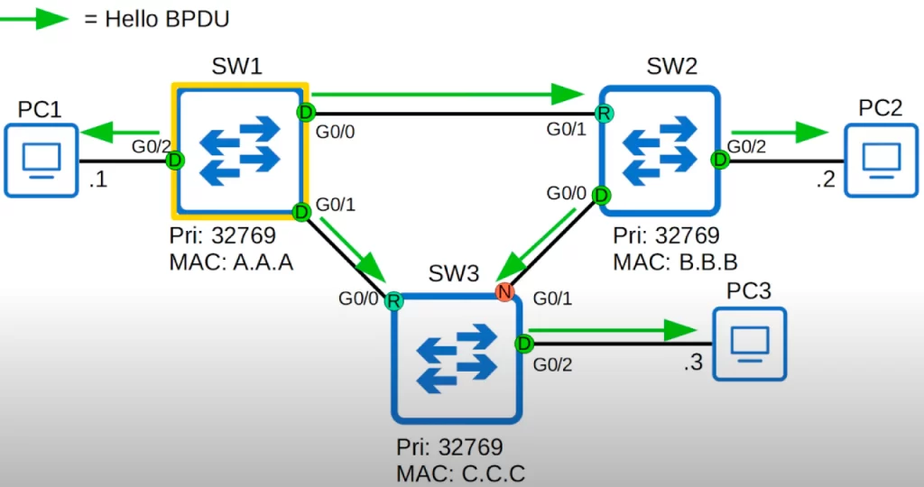
After 2 seconds, the root bridge will send BPDUs again, and the other switches will again forward these BPDUs on their designated ports.
Next up, the forward delay timer.
This is the length of the listening and learning transitional states that a port goes through when it moves to forwarding.
This is not the total length of both transitional states combined. With the default forward delay timer of 15 seconds for each state, it takes a total of 30 seconds for the switch port to move through both states and forward traffic.
The final timer is the max age timer.
This timer indicates how long an interface will wait to change the Spanning Tree topology after ceasing to receive Hello BPDUs. The timer is reset every time a BPDU is received.
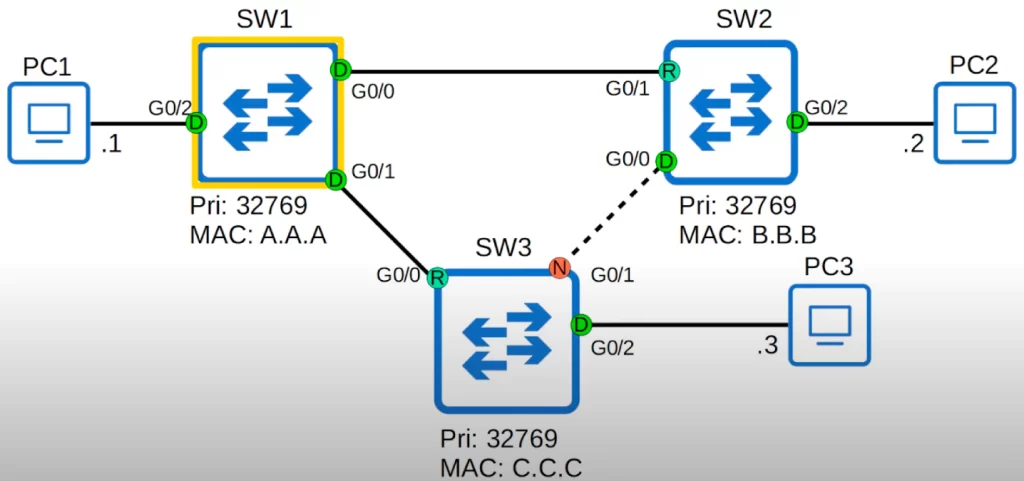
Each collision domain has one designated port. BPDUs are forwarded out of designated ports. All root ports and non-designated ports expect to receive BPDUs.
The root bridge, SW3, sends BPDUs, and then SW1 and SW4 forward them out of their designated ports.
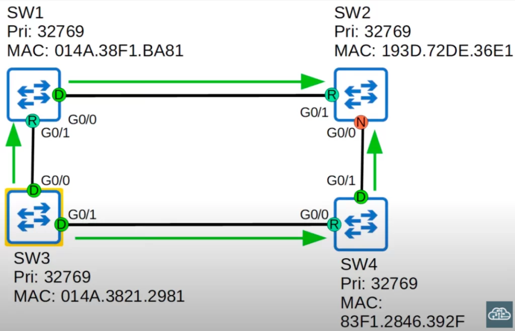
To demonstrate how the max age timer works, let’s focus on SW2’s G0/1 interface. It just received a BPDU, so the max age timer of SW2’s G0/1 interface is reset to 20. It counts down to 18. And then the root bridge sends BPDUs, because of the 2 second hello timer. SW2 resets its max age timer to 20. It starts counting down again: 19, 18. And on and on it goes.
Suppose a failure occurs on the connection between SW1 and SW2, and SW1’s G0/0 interface goes down. The root bridge will send BPDUs, and other switches will forward the BPDUs. Because SW1’s G0/0 interface is down, SW2 no longer receives a BPDU on its G0/1 interface.
So the max age timer continues counting down. 17, 16, 15 … and if the failure does not recover and SW2 does not receive any more BPDUs on its G0/1 interface, SW2’s max age timer will count all the way down to 0. What happens next?
*If another BPDU is received before the max age timer counts down to 0, the time will reset to 20 seconds and no changes will occur.
*However, if another BPDU is not received and the max age timer counts down to 0, SW2 will reevaluate its STP choices, including root bridge, and local root, designated, and non-designated ports.
*After these decisions, if a non-designated port is selected to become a designated or root port, the port will transition from the blocking state to the listening state (for 15 seconds), learning state (again for 15 seconds), and then finally the forwarding state. So it can take a total of 50 seconds for a blocking interface to transition to forwarding.
A blocking interface cannot move directly to forwarding state. It must go through the listening and learning states.
However, a forwarding interface can move directly to a blocking state, since there would be no concern about creating a loop by blocking an interface.
These timers and transitional states are meant to make sure that loops are not accidentally created by an interface moving to a forwarding state too soon.
STP BPDU (Bridge Protocol Data Unit)
Let’s look at a Spanning Tree BPDU Wireshark packet capture. Let’s explore what fields are included in the STP BPDU and what is their purpose.
BPDUs are encapsulated in an Ethernet frame. In the Ethernet frame, the BPDU is located in the LLC (logical link control) header.
The following diagram shows an Ethernet frame with a BPDU:
Destination MAC Address | Source MAC Address | 802.1Q VLAN tag | EtherType | LLC (2 bytes) | BPDU (20 bytes) | FCS
In the case of BPDUs, the LLC header will have a value of 0x0800. The BPDU frame contains information about the switch that is sending the BPDU, such as the MAC address, Bridge ID, and port ID. The BPDU also contains information about the network topology, such as the identity of the root bridge and the cost of each port.
The BPDU frame contains 12 distinct fields that are used to convey path and priority information that STP uses to determine the root bridge and paths to the root bridge.
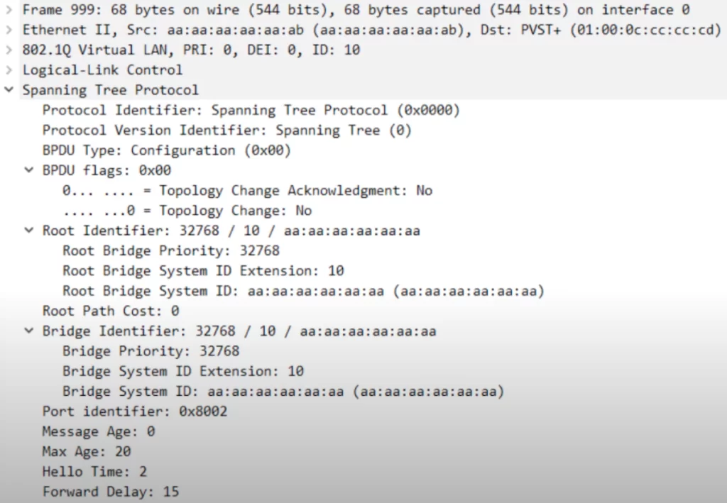
First off, in the Ethernet header section, notice the destination (Dst). A switch sends BPDUs using the source MAC address from its origin port to a multicast address with a destination MAC of 01:00:0C:CC:CC:CD for Cisco proprietary PVST+. Regular Spanning Tree uses a destination MAC address of 01:80:c2:00:00:00, a multicast address. Remember these MAC addresses for the CCNA exam.
Let’s look at the BPDU itself (section “Spanning Tree Protocol”).
>The first three fields are: 1) the Protocol Identifier, which is always hexadecimal 0000 for Spanning Tree; 2) the Protocol Version Identifier is set to 0 for classic Spanning Tree (the protocol version in an RSTP BPDU is 2); and 3) the BPDU Type is hexadecimal 00 for what is called a Configuration BPDU.
>Next up are BPDU flags. These are used to signal topology changes to other switches.
>Next up is the Root Identifier, which gives the bridge priority, extended system ID (the VLAN ID), 10 in this case, and the bridge system ID, which is the MAC Address of the root bridge. The MAC address is set to all a’s in this case.
>Next is the Root Path Cost. It is 0 in this case, so you know that this is the root bridge. You can also know that this is the root bridge by looking at the information in the Bridge Identifier field. The information in the Bridge Identifier field is the same as in the Root Identifier field, so this is the root bridge.
>Next is the Port identifier (Port ID), the port that sent the BPDU. It is hexadecimal 8002. 80 in hexadecimal is equivalent to 128, which is the default port priority. 02 is the number of the port itself.
>Finally, the timers: Message Age, Max Age, Hello Time, and Forward Delay. We have not discussed message age, but it is essentially the time it takes for a BPDU to expire and has a default value of 20 seconds.
The STP timers on the root bridge determine the STP timers for the rest of the switches in the network, even if they are configured differently.
STP optional features (STP Toolkit)
STP optional features, sometimes called STP Toolkit, are additional features that can be enabled on switches to improve the functionality (performance, security, and reliability) of STP. Some of the most common STP optional features include PortFast, BPDU Guard, and Root Guard.
STP Toolkit PortFast
PortFast solves one problem of Spanning Tree. PortFast allows a switch port to transition to the forwarding state immediately, bypassing the listening and learning states. This can be useful for connecting end devices to a switch, as it allows them to access the network more quickly.
PortFast can be enabled on interfaces connected to end hosts, like the G0/2 interface on each of these switches (the red boxes). These are designated ports, in a forwarding state.
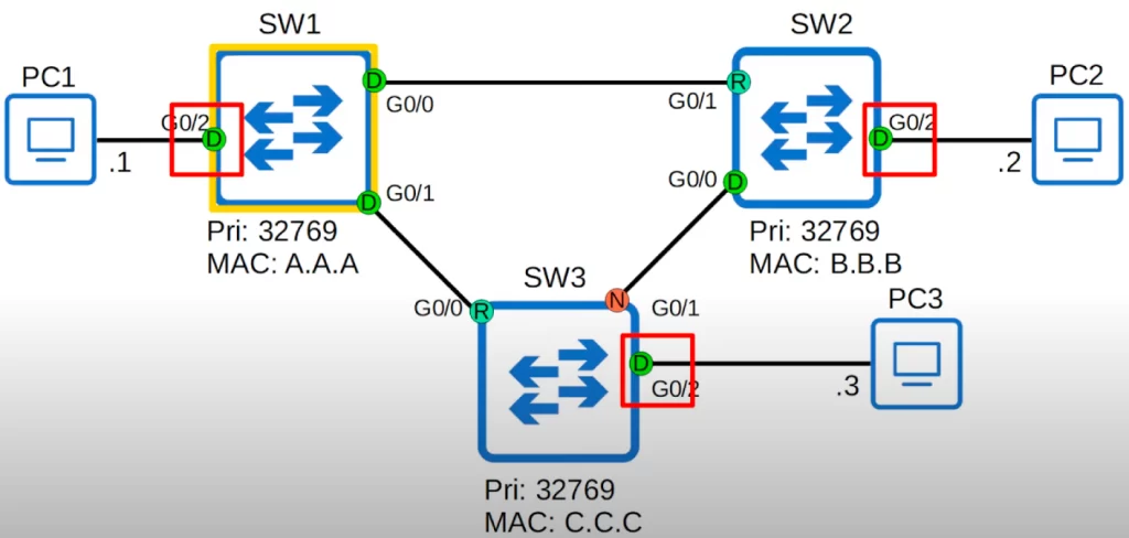
When interfaces are first turned on or first connected to the PCs, they must first go through the listening and learning states before they can start forwarding traffic. This process takes 30 seconds in total.
Since only interfaces connected to another switch can form a Layer 2 loop, there is no risk of forming a loop with an end host. So there is no point in making these ports wait 30 seconds to transition to forwarding.
If used, PortFast must be enabled only on ports connected to end hosts. If enabled on a port connected to another switch it could cause a Layer 2 loop.
PortFast is enabled at the interface level with the command spanning-tree portfast.
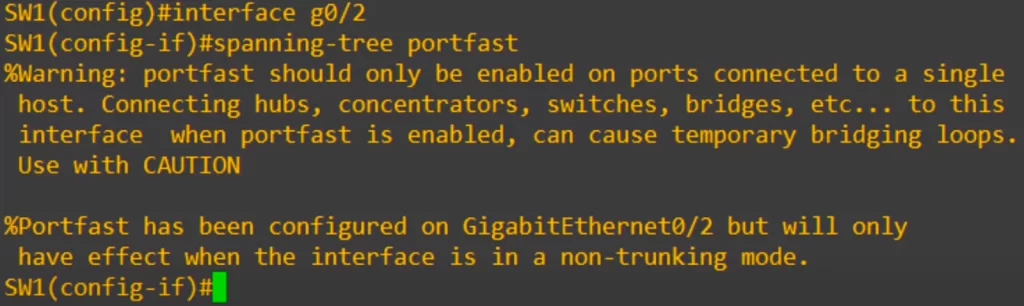
When we enter the command we get a warning that PortFast should only be enabled on ports connected to an end host. There is also a message saying that even though portfast was configured, it will only take effect if the interface is in a non-trunking mode (so if it is an access port). This is because trunk ports are typically connected to other switches. If you configure PortFast on a trunk port, you will get no effect.
You can also enable PortFast with the following command in global config mode:
SW1(config)#spanning-tree portfast default
This enables PortFast on all access ports, but not trunk ports.
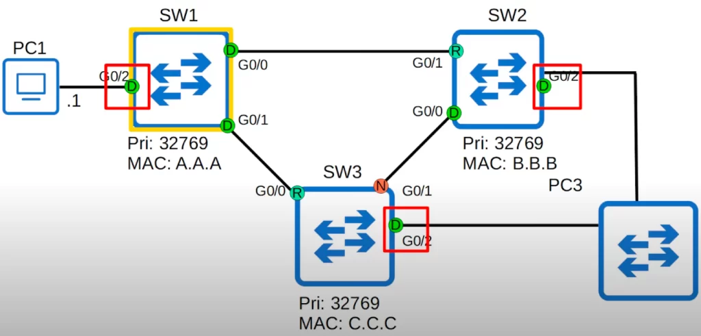
PortFast can be a risk. Consider what may happen if an employee plugged another switch into the network, as shown below. Because PortFast is putting these interfaces into a forwarding state, a Layer 2 loop will form. However, the BPDU Guard optional feature can prevent such a loop from forming.
STP Toolkit BPDU Guard
If an interface with BPDU Guard enabled receives a BPDU from another switch, the interface will be shut down to prevent a loop from forming.
PortFast speeds up port transition to forwarding state on access ports (typically connecting to end devices). However, PortFast ideally should not receive BPDUs used in STP communication. BPDU Guard listens for BPDUs on PortFast enabled ports.
If BPDU Guard detects a BPDU on a PortFast port, it assumes an issue like an unauthorized device connecting to the switch port. It then disables the port to prevent potential loops and security risks.
You can configure BPDU Guard on a switch interface using the command spanning-tree bpduguard enable.
SW1(config)#interface g0/2
SW1(config-if)#spanning-tree bpduguard enable
Similar to PortFast, there is also an option to enable it by default. From global config mode:
SW1(config)#spanning-tree portfast bpduguard default
This enables BPDU guard on all portfast-enabled interfaces.
The following screenshot was taken from Packet Tracer. A switch was connected to a BPDU-guard enabled interface, and now you can see what happens when a BPDU arrives on a BPDU guard-enabled port.
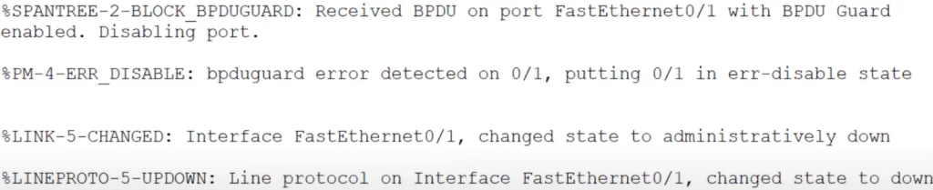
The port is disabled, effectively shut down.
To enable a port that was disabled by BPDU guard, use the commands shutdown, and then no shutdown on the interface.
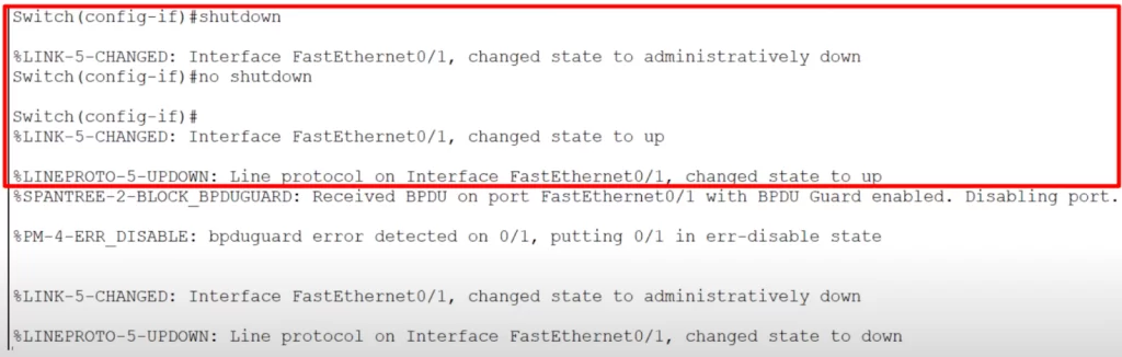
The interface comes up.
In terms of Spanning Tree optional features, the CCNA 200-301 exam topics list only mentions PortFast:
2.0 Network Access
2.5 Interpret basic operations of Rapid PVST+ Spanning Tree Protocol
2.5.a Root port, root bridge (primary/secondary), and other port names
2.5.b Port states (forwarding/blocking)
2.5.c PortFast
BPDU Guard has a practical connection to PortFast, so BPDU Guard is likely included.
STP Toolkit Root Guard/Loop Guard
There are many other optional features that can be enabled on a switch. Let’s introduce two other optional features in case they show up in the exam, Root Guard and Loop Guard.
1) Root Guard: If a switch receives a superior BPDU (with a lower Bridge ID) than the current root bridge on the Root Guard enabled port, the switch will not accept the new switch as the root bridge. The interface will be disabled. This helps maintain the Spanning Tree topology if someone plugs another switch into the network either with bad intent, or perhaps without knowing the impact of their action.
Configure Root Guard from interface configuration mode: spanning-tree guard root
Enable Root Guard on specific ports where you want to enforce the designated root bridge location.
Verify the configuration: show spanning-tree interface interface and show spanning-tree guard
2) Loop Guard: If you enable loop guard on an interface, even if the interface stops receiving BPDUs, it will not start forwarding. The interface will be disabled. This prevents loops that can happen if an interface fails only in one direction, causing what is called a unidirectional link that cannot receive data, but is still able to forward it, or the opposite.
STP configuration – mode (MST, PVST+, Rapid PVST+)
STP runs by default so you do not actually have to do any configuration, but you should know how to change which switch becomes the root switch to make sure traffic follows the best path.
Let’s look at some basic STP configurations, starting with the mode. You can configure the spanning mode the switch uses with the command spanning-tree mode.
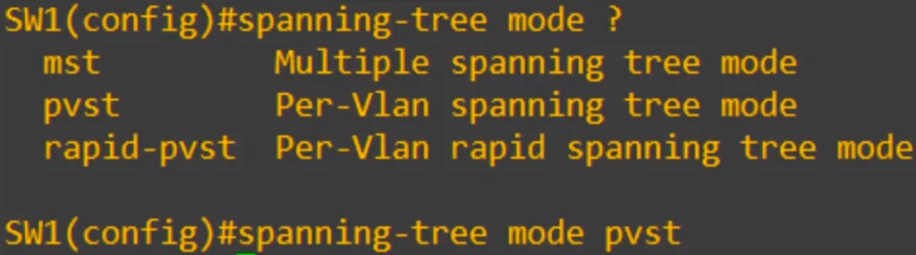
We have three options.
MST (multiple spanning tree), a topic beyond the scope of the CCNA.
PVST is a Cisco proprietary STP version that runs a separate instance of STP for each VLAN. This allows for different root bridges and port roles to be configured for each VLAN.
Rapid PVST is also a Cisco proprietary STP version that runs a separate instance of STP for each VLAN. However, it uses a faster convergence algorithm than PVST, which can help to improve network availability in the event of a failure.
Note: references to PVST are references to PVST+, since PVST per se (which preceded PVST+) is dead and buried. RSTP (rapid STP) is sometimes used to refer to Rapid PVST (i.e., Rapid PVST+).
Modern Cisco switches run Rapid PVST by default, and usually there is no reason to change it.
STP configuration – root bridge
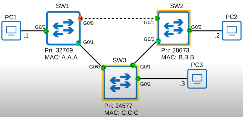
You can manually configure the root bridge by manipulating the Bridge Priority of a switch. With these MAC addresses and the default priority values, SW1 is the root bridge.
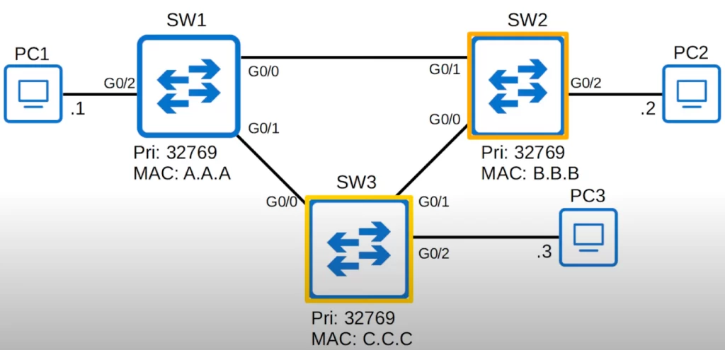
However, we could configure SW3 to be the root bridge. We could also configure SW2 to be a secondary root bridge, which will be next in line to become the root bridge if the current root bridge fails.
Let’s see how to do these configurations. This is how to configure the root bridge, called the primary root bridge: spanning-tree vlan vlan-number root primary.
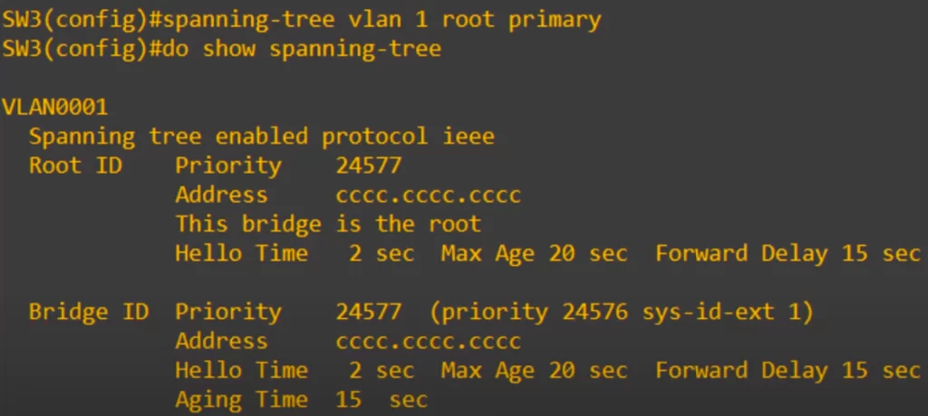
Note the root ID and Bridge ID matching information, indicating a successful configuration. And it also says “This bridge is the root”.
The spanning-tree vlan vlan-number root primary command (the spanning-tree root command) sets the STP priority to 24576. If another switch already has a priority lower than 24576, the command sets this switch’s priority to 4096 less than the other switch’s priority. So the command makes this switch have the lowest priority, making it the root bridge.
If you then check the running-config, you can see that the command that is actually applied in this case is spanning-tree vlan 1 priority 24576.
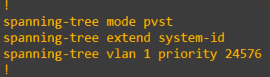
So this command tells the switch to apply the spanning-tree priority command, either with the priority 24576, or 4096 less than the current lowest priority.
The command to set the secondary root bridge, the bridge with the second-lowest priority, is basically the same.
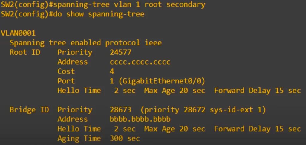
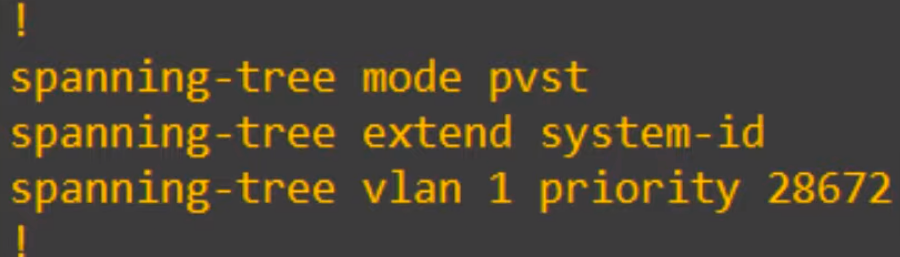
The spanning-tree vlan vlan-number root secondary command sets the spanning tree priority for this VLAN to 28672 (24576 + 4096).
However, like the root primary command, the actual command that is applied is the spanning-tree priority command.
For both of these commands, you could actually use the spanning-tree priority command as you see here to configure the root bridge. The spanning-tree root command is just a simple way to do it without remembering the different increments of 4096 of the bridge priority.
STP load balancing
The interface between SW1 and SW2 is disabled because SW1 is blocking its G0/0 interface.
This topology is running Cisco’s PVST+, so this is the topology for VLAN1.
Perhaps there is another VLAN, VLAN 2, in this topology. What will the topology look like for it?
It will look like this, the default topology, because the root bridge settings we configured only apply to VLAN 1.
In VLAN 2, the connection between SW1 and SW2 will not be disabled, but the connection between SW2 and SW3 will be disabled. This allows for Spanning Tree load balancing.
If you have multiple VLANs in your network, blocking the same interface in each VLAN is a waste of interface bandwidth. That connection will be sitting idle, just waiting for another connection to fail so it can take over and start forwarding. However, if you configure a different root bridge for different VLANs, different VLANs will disable different interfaces.
To check if you understood that explanation, ponder this. We want to make SW1 the primary root bridge for VLAN10 and the secondary for VLAN20, so essentially it acts like a backup root bridge for VLAN20.
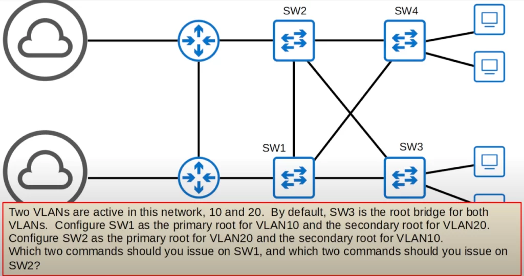
We can configure SW1 and SW2 using the spanning-tree root commands.
So here are the commands to issue on SW1.
SW1(config)#spanning-tree vlan 10 root primary
SW1(config)#spanning-tree vlan 20 root secondary
On SW2 we want to do the opposite. We want to configure SW2 to be the root bridge for VLAN20 and the secondary root bridge for VLAN10, so SW2 will have the second lowest priority in VLAN10 and become the root for VLAN10 if SW1 fails.
Here are the commands to issue on SW2, basically the opposite of SW1.
SW2(config)#spanning-tree vlan 20 root primary
SW2(config)#spanning-tree vlan 10 root secondary
This way of configuring STP makes it possible to load balance by blocking different ports in each VLAN, in each STP instance. We can use our network bandwidth more effectively since we do not have any connections going totally unused just waiting for another connection to fail.
With those settings, perhaps the VLAN10 topology looks like this.
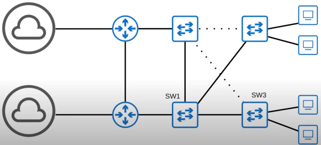
And then perhaps the VLAN20 topology looks like this.
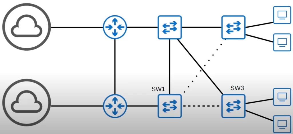
Different connections are used in different VLANs, allowing the load to balance across different interfaces. This is called load balancing.
Configuring STP port settings
There are two main settings you can configure on a Spanning Tree port: the root cost and the port priority. As you can see from this command they are both configured on a per-VLAN basis like the bridge priority.
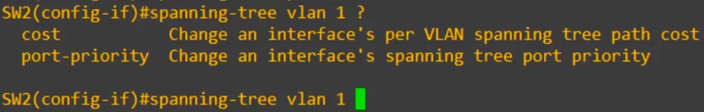
“cost” is the root cost. Recall from STP Part 1, FastEthernet costs 19, Gigabit Ethernet costs 4, etc. Cost is used to determine the root port, and is also used in selecting designated and non-designated ports.
Recall from STP Part 1, port priority is the first half of the STP port ID, which is the final tiebreaker in determining the root port. The STP port ID equals the port priority plus the port number.
You may want to change the root cost or the port priority in order to change the result of the root port or designated port selection process.
The cost and priority are the only spanning tree interface settings you need to know for the CCNA.
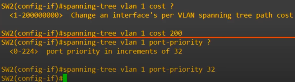
First, the cost was configured for this interface. As you can see the range is from 1 to 200 million. Then we set the port priority, which is configured in increments of 32, from 0 to 224.
Command review
>To enable PortFast on a switch:
SW(config-if)#spanning-tree portfast
→to enable PortFast on a switch interface
SW(config)#spanning-tree portfast default
→to enable PortFast on all access ports
>To configure BPDU Guard on a switch:
SW(config-if)#spanning-tree bpduguard enable
→to configure BPDU Guard on a switch interface
SW(config)#spanning-tree portfast bpduguard default
→to enable BPDU guard on all portfast-enabled interfaces
>To enable a port that was disabled by BPDU guard:
SW(config-if)#shutdown
SW(config-if)#no shutdown
>STP mode (MST, PVST+, Rapid PVST+):
SW(config)#spanning-tree mode ?
mst
pvst
rapid-pvst
>Root bridge configuration:
You can manually configure the root bridge by manipulating the (4-bit) bridge priority of a switch.
SW(config)#spanning-tree vlan vlan-number root primary
→to configure the primary root bridge using the spanning-tree root command. You can check the running-config to see the spanning-tree priority command that was actually applied
SW(config)#spanning-tree vlan vlan-number root secondary
→to set the secondary root bridge
SW#show spanning-tree
SW#show spanning-tree vlan vlan-number
>STP load balancing (example):
The commands to issue on SW1 and SW2 to make SW1 the primary root bridge for VLAN10 and the secondary for VLAN20, and SW2 the primary root bridge for VLAN20 and the secondary for VLAN10:
SW1(config)#spanning-tree vlan 10 root primary
SW1(config)#spanning-tree vlan 20 root secondary
→the commands to issue on SW1
SW2(config)#spanning-tree vlan 20 root primary
SW2(config)#spanning-tree vlan 10 root secondary
→the commands to issue on SW2 (basically the opposite of SW1)
>Configuring STP port settings (example):
There are two main settings you can configure on a Spanning Tree port: the root cost and the port priority (the first half of the port ID, having a default value of 128). They are both configured on a per-VLAN basis like the bridge priority.
The root cost and port priority are the only Spanning Tree interface settings you need to know for the CCNA.
SW2(config-if)#spanning-tree vlan 1 ?
cost
port-priority
SW2(config-if)#spanning-tree vlan 1 cost ?
<1 – 200000000>
SW2(config-if)#spanning-tree vlan 1 cost 200
SW2(config-if)#spanning-tree vlan 1 port-priority ?
<0 – 224>
SW2(config-if)#spanning-tree vlan 1 port-priority 32
Free CCNA | Configuring STP (PVST+) | Day 21 Lab – Notes
Key learnings
*STP states and timers.
*STP BPDU: the structure of a spanning tree BPDU – what fields are included in it and what their purpose is.
*STP optional features: PortFast and BPDU Guard.
*STP configuration: some basic Spanning Tree configurations, including configuring the root bridge, using different root bridges in different VLANs to achieve load balancing across different interfaces, and some basic Spanning Tree interface settings.
Key references
Note: The resources cited below (in the “Key references” section of this document) are the main source of knowledge for these study notes/this lesson, unless stated otherwise.
Free CCNA | Spanning Tree Protocol (Part 2) | Day 21 | CCNA 200-301 Complete Course
Free CCNA | Configuring STP (PVST+) | Day 21 Lab | CCNA 200-301 Complete Course
Other references/resources
Related content
Basic operations of Rapid PVST+ STP
Compliance frameworks and industry standards
How data flow through the Internet
How to break into information security
IT career paths – everything you need to know
Job roles in IT and cybersecurity
Network security risk mitigation best practices
STP root bridge election and root port selection
The GRC approach to managing cybersecurity
The penetration testing process
The Security Operations Center (SOC) career path
Back to DTI Courses


