This lesson constitutes Part 2 of 4 of the wireless networking series of lessons for the CCNA. In the previous lesson (Part 1), Wireless fundamentals for the CCNA, we learned about how a single access point (AP) can provide a basic service set (BSS) for a cell area, and how multiple APs can be connected to form an extended service set (ESS) for a larger network. This lesson dives deeper into wireless network architectures, specifically, this lesson focuses on the topics listed under Section 2, Network Access, subsection 2.6, of the CCNA exam topics list, which says you must be able to “Compare Cisco Wireless Architectures and AP modes”.
Part 3, Wireless network security, examines various methods for securing a wireless network, covering a lot of authentication methods and encryption and message integrity algorithms. Part 4, Configure WLAN within the GUI using WPA2 PSK, explains how to configure and verify WLAN within the GUI using WPA2 PSK.
This lesson first discusses the autonomous AP architecture. This is followed by a discussion of the cloud-based AP architecture, and then a discussion of split-MAC architectures. Wireless LAN controller deployments are then compared. Finally, Cisco AP modes are explored. This write up is based on Chapter 27, Analyzing Cisco Wireless Architectures, of the CCNA 200-301 Official Cert Guide by Odom (2020). As we explore each architecture type, attention is given to details that permit us to technically analyze wireless network architectures in terms of scalability, management, deployment and troubleshooting, and how the APs can be controlled. This post constitutes Issue 42 of my CCNA 200-301 study notes.
- Autonomous AP architecture
- Cloud-based AP architecture
- Split-MAC architectures
- WLC deployment models
- Cisco AP modes
- Practice quiz questions
- Key references
You may also be interested in CCNA wireless networking portal.
Autonomous AP architecture
A primary function of an AP is to bridge wireless data from the air to a wired network. APs control client access to the wireless LAN (WLAN). An AP can allow wireless clients to connect to a LAN by accepting their connections, just as if clients were using wired connections.
Autonomous APs form one or more fully functional standalone BSSs. APs extend a switched network, connecting SSIDs to wired VLANs at the access layer.
An AP performs a number of important functions in a BSS:
- Layer 2 bridging: APs do L2 encapsulation and de-encapsulation. This is how they are able to connect wireless devices to a wired network. An AP receives wireless frames from clients and encapsulates them in Ethernet frames before sending them to the wired network. Similarly, the AP receives Ethernet frames from the wired network and decapsulates them before sending them to the appropriate wireless client.
- Authentication and encryption: the AP is responsible for authenticating and encrypting wireless traffic to help protect the data from unauthorized access.
- Signalling: the AP handles the signalling between wireless clients and the wired network. This includes things like sending beacon frames to announce the presence of the BSS and responding to probe requests from clients.
- Radio resource management: the AP manages the radio resources in the BSS. This includes things like allocating channels to clients and coordinating the use of the airwaves.
In addition to these tasks, the AP can also provide a number of other features, such as:
- Wireless security: the AP can be configured to use different wireless security protocols, such as WPA2 and WPA.
- Quality of service (QoS): the AP can be configured to provide QoS for different types of traffic. This can be useful for things like streaming video or VoIP calls.
- Roaming: the AP can help clients roam between APs as they move around. This helps to ensure that clients always have a good connection to the network.
What defines the architecture of an enterprise network using autonomous APs? What connections, components, and services are involved?
Figure 27-1 shows how autonomous APs comprise the basic architecture of an enterprise network. A typical enterprise network could consist of hundreds or thousands of APs. The APs and their data connections are distributed across the coverage area and across the network.
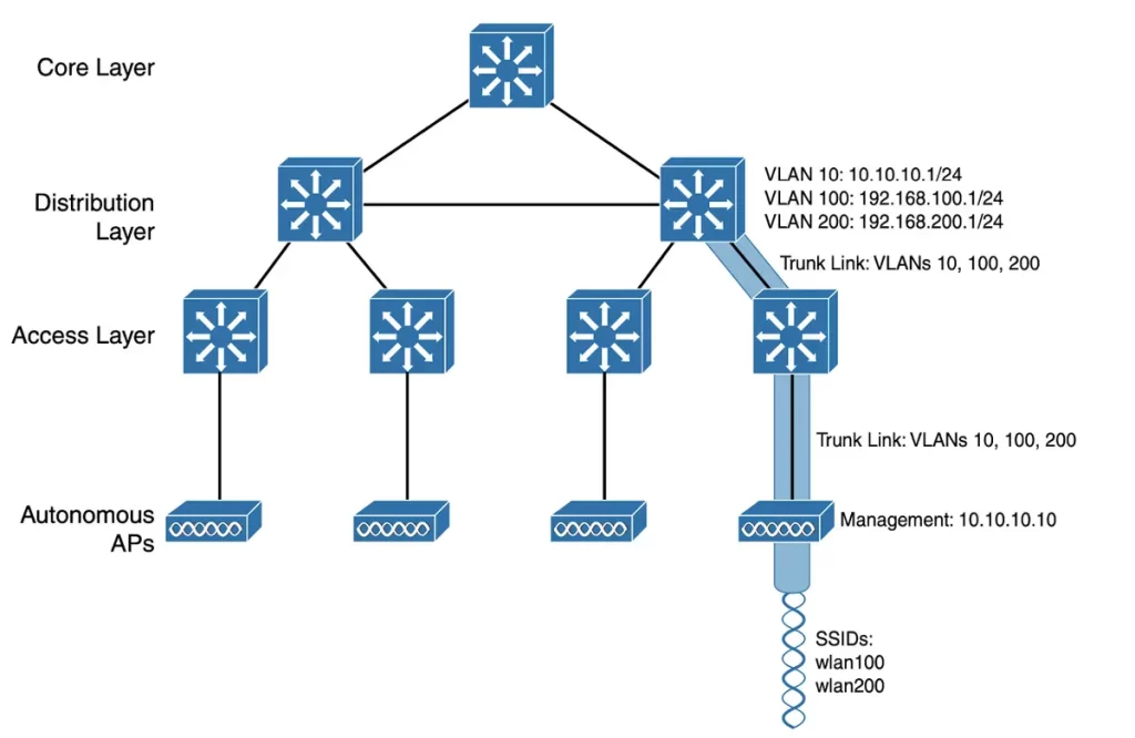
>The wireless network in Figure 27-1 consists of two SSIDs, wlan100 and wlan200, corresponding to two wired VLANs, 100 and 200, respectively.
>The VLANs must be trunked from the distribution layer switch (where routing commonly takes place) to the access layer. From the access layer, VLANs extend further over a trunk link to the AP.
>An autonomous AP offers a quick path for data to travel between the wireless and wired networks. Data has to travel only through the AP to reach the other side of the network. Two wireless users associated with an autonomous AP can reach each other through the AP without communication having to pass up into the wired network.
>An autonomous AP is configured with a management IP address (10.10.10.10) for remote management – SSIDs, VLANs, and RF parameters such as the channel and transmit power need to be configured. The management address is not included in any of the data VLANs by default. To access the AP, a dedicated management VLAN (VLAN 10) must be added to the trunk links.
>Each AP must be configured and maintained individually, unless you use a management platform such as Cisco Prime Infrastructure or Cisco DNA Center.
You will likely want to offer the same SSID on your APs so that wireless clients can associate with that SSID throughout the service coverage area. You may want to extend the corresponding VLAN and IP subnet to each AP so that clients do not have to request a new IP address for each new association.
An important network architecture consideration is that SSIDs and their VLANs must be extended at Layer 2. Figure 27-2 shows how VLANs and SSIDs extend in an autonomous AP architecture. From top to bottom, follow VLAN 100 as it reaches through the network.
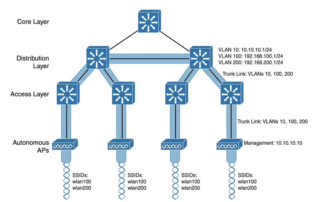
VLAN 100 is routed within the distribution layer and must be extended via trunk links to the access layer switches and then to each autonomous AP. So VLAN 100 extends end to end across the entire infrastructure—not exactly a best practice.
Consider the challenges when you have to add a new VLAN and configure every switch and AP in the network to carry and support it. The challenges grow if the network has redundant links between each layer of switches.
The Spanning Tree Protocol (STP) running on each switch becomes a vital ingredient to prevent bridging loops from forming and corrupting the network. For these reasons, client roaming across autonomous APs is typically limited to the Layer 2 domain, or the extent of a single VLAN. As the wireless network expands, the infrastructure becomes more difficult to configure correctly and becomes less efficient. (p. 689)
Cloud-based AP architecture
An autonomous AP architecture requires considerable configuration and management. Each AP must be configured and maintained individually. To manage a growing number of autonomous APs, you could use an AP management platform, such as Cisco Prime Infrastructure, located centrally within the enterprise. This would require purchasing, configuring, and maintaining the platform.
A cloud-based AP architecture would offer a simpler network management approach. The AP management function would be pushed out of the enterprise and into the Internet cloud. Cisco Meraki offers cloud-based centralized management of wireless, switched, and security networks built from Meraki products. Meraki’s cloud networking service allows you to configure and manage APs, monitor wireless performance and activity, and generate reports.
Cisco Meraki APs can be deployed automatically. When an AP powers up it contacts the cloud and self-configures. You can then manage the AP through the Meraki cloud dashboard.
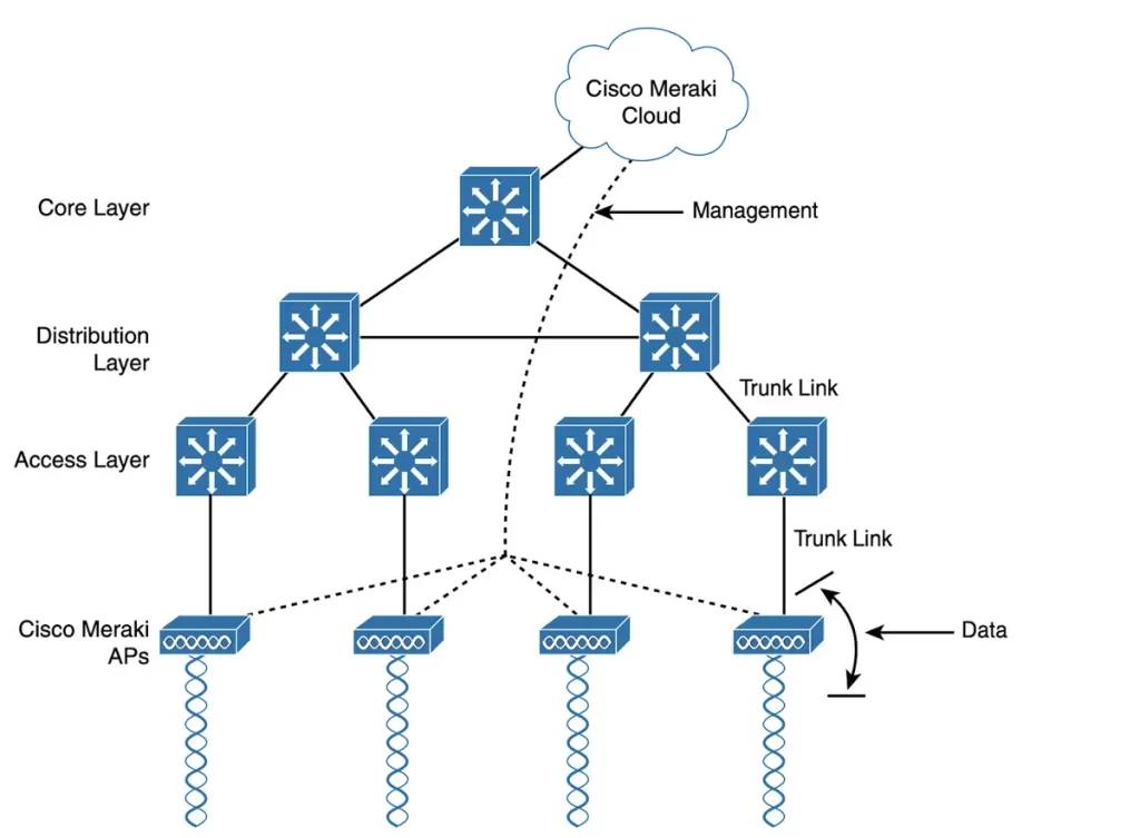
Figure 27-3 illustrates the basic cloud-based architecture. All of the APs are managed, controlled, and monitored centrally from the cloud. The network has an identical arrangement to that of an autonomous AP network, as the APs in a cloud-based network are all autonomous too.
The Cisco Meraki cloud allows you to,
- upgrade code and configure changes to the APs,
- add the intelligence needed to automatically instruct each AP on which channel and transmit power level to use, and
- collect information from the APs about deployment performance and operations, such as wireless usage statistics, RF interference, rogue or unexpected wireless devices that were overheard, and wireless usage statistics.
In the cloud-based architecture, the data path from the wireless network to the wired network is very short. The data of wireless clients does not have to travel to the cloud and back.
A cloud-based network (seen in Figure 27-3) consists of two distinct paths (this division will become important as other types of architecture are discussed):
*Data plane: The data path is where the actual data flows between the endpoints of the network. This is the path that end-user traffic takes when it passes through the AP. The data plane is responsible for routing and forwarding traffic to its destination.
*Management plane: The control plane is responsible for managing the AP’s configuration, security, and performance. The control path is where the network devices exchange information about the state of the network and how to forward traffic. The control path is responsible for managing the data path. The control plane is responsible for managing network topology, routing protocols, and other network services.
The separation of the data plane and the control plane is a key design principle of cloud-based networks. It helps to improve performance, security, and scalability.
Performance: the data plane and the control plane can be optimized for their respective tasks. The data plane can be optimized for high throughput and low latency, while the control plane can be optimized for security and reliability.
Security: by separating the data plane and the control plane, it is possible to isolate management traffic from end-user traffic. This helps to protect the AP from unauthorized access and attack.
Scalability: the separation of the data plane and the control plane makes it easier to scale the AP. As the number of users increases, the data plane can be scaled out by adding more APs. The control plane can be scaled out by adding more controllers.
In a cloud-based network, the data plane is typically implemented in the cloud. The control plane is typically implemented in the AP itself. The cloud-based network controller is responsible for managing the APs in the network.
Split-MAC architectures
Managing the RF operation of autonomous APs can be a challenge for network admins, as it involves selecting and configuring the channel used by each AP, detecting and removing rogue APs that might be interfering, and managing transmit power level to ensure sufficient and efficient wireless coverage even when an AP’s radio fails.
Managing wireless network security can also be a challenge since each autonomous AP manages its own security policies, and there is no central point of entry between the wireless and wired networks – no convenient place to monitor traffic and deploy intrusion detection and prevention, quality of service, bandwidth policing, and so on.
If we shift some functions within autonomous APs to a central location it would help overcome the limitations/management challenges of distributed autonomous APs.
Figure 27-4 shows how most of the activities performed by an autonomous AP (on the left) can be broken up into two groups—management functions on the top and real-time processes on the bottom.
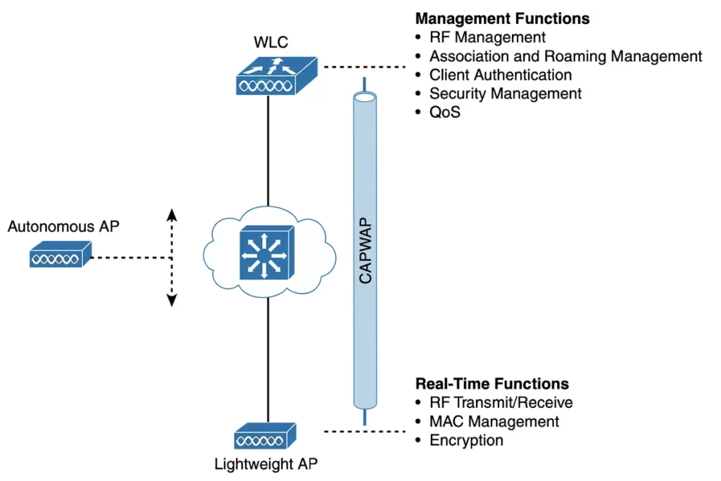
The real-time processes include encryption on a per-packet basis, and sending and receiving 802.11 frames, beacons, and probe messages. The AP must interact with wireless clients at the Access Control (MAC) layer. This function must remain with the AP hardware, closest to the clients.
On the other hand, management functions are not integral to handling frames over the RF channels, so these functions can be administered from a centrally located platform aways from the AP.
When the functions of an autonomous AP are split, the AP hardware is referred to as a lightweight access point (LAP), and it only performs real-time 802.11 operations.
Typically, the management functions are performed on a wireless LAN controller (WLC), which controls many LAPs. The AP retains duties in Layers 1 and 2, where frames are moved into and out of the RF domain. A LAP becomes completely dependent on the WLC for every other WLAN function, such as authenticating users, managing security policies, and selecting RF channels and output power. A FlexConnect architecture is an exception to this dependency.
The lightweight AP-WLC division of labor is known as a split-MAC architecture, where the normal MAC operations are pulled apart into two distinct locations. This occurs for every AP in the network; each one must boot and bind itself to a WLC to support wireless clients. The WLC becomes the central hub that supports a number of APs scattered about in the network. (p. 693)
A LAP binds with a WLC to form a complete working access point by using a tunneling protocol to carry 802.11-related messages and client data between the two devices.
While the AP and WLC can be located on the same VLAN or IP subnet, they do not have to be. They can be located on two entirely different IP subnets in two entirely different locations.
The Control and Provisioning of Wireless Access Points (CAPWAP) tunneling protocol encapsulates the data between the LAP and WLC within new IP packets. The tunneled data can then be switched or routed across the network.
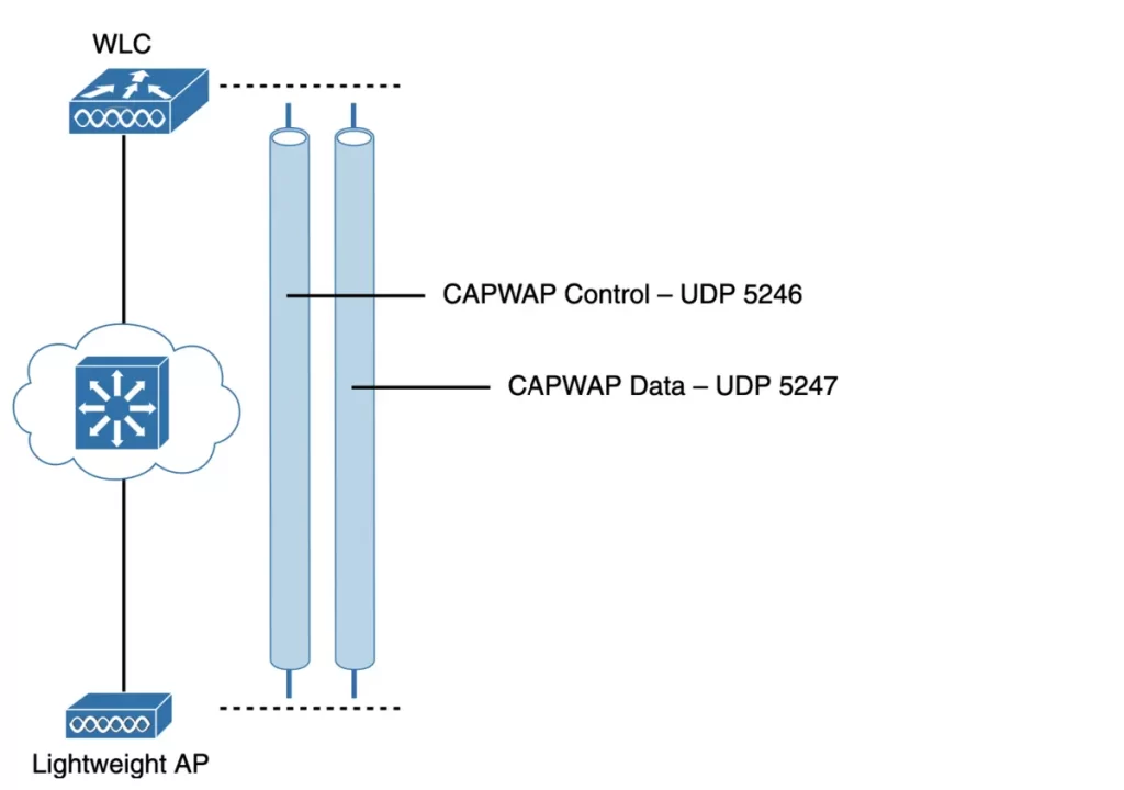
As Figure 27-5 shows, the CAPWAP relationship consists of two separate tunnels:
■ CAPWAP control: carries exchanges that are used to configure the AP and manage its operation. The control messages are authenticated and encrypted, so the AP is securely controlled by only the appropriate WLC, then transported over the control tunnel.
■ CAPWAP data: used for packets traveling to and from wireless clients associated with the AP. Data packets are transported over the data tunnel but are not encrypted by default. When data encryption is enabled for an AP, packets are protected with Datagram Transport Layer Security (DTLS).
CAPWAP is based on the Lightweight Access Point Protocol (LWAPP), a legacy Cisco proprietary solution. CAPWAP is defined in RFCs 5415, 5416, 5417, and 5418.
Every device is authenticated before becoming part of the wireless network. APs and WLCs use digital certificates to authenticate each other. An X.509 certificate is preinstalled in each device when it is purchased.
The CAPWAP tunneling allows the geographic and logical separation between the AP and WLC, and breaks the dependence on Layer 2 connectivity between them.
Notice in Figure 27-6 the extent of VLAN 100 – how it exists as SSID 100 near the wireless clients—but not in between the AP and the WLC. The traffic of clients associated with SSID 100 is transported across the network infrastructure encapsulated inside the CAPWAP data tunnel.
The tunnel extends from the IP address of the WLC and the IP address of the AP, which allows all of the tunneled packets to be routed at Layer 3.
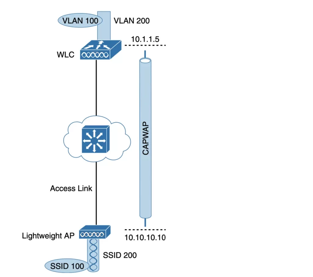
Because the AP sits on the access layer where its CAPWAP tunnels terminate, only one IP address (10.10.10.10) can be used for both management and tunneling. The AP does not have a trunk link because all of the VLANs it supports are encapsulated and tunneled as Layer 3 IP packets, rather than individual Layer 2 VLANs.
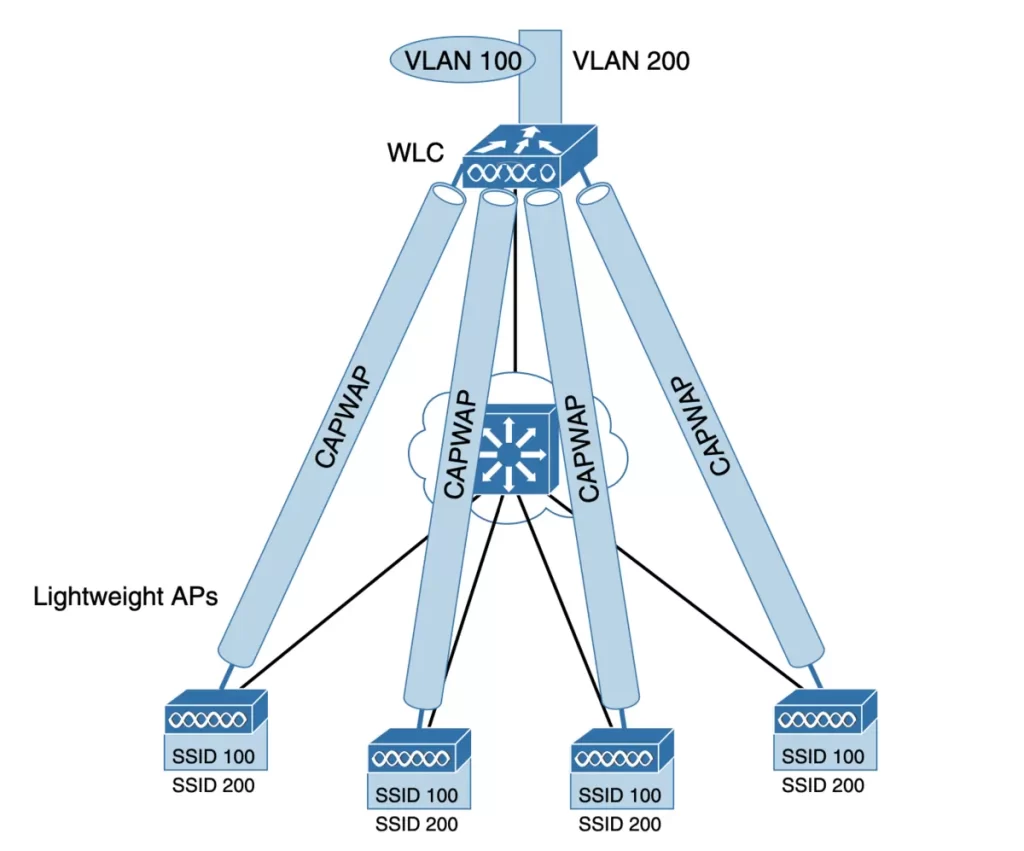
As the wireless network grows, the WLC builds more CAPWAP tunnels to reach more APs. The network in Figure 27-7 has four APs, each AP has a control and a data tunnel to the centralized WLC. SSID 100 can exist on every AP. VLAN 100 can reach every AP through the tunnels.
Once CAPWAP tunnels are established between a WLC and one or more lightweight APs, the WLC can offer several additional functions.
Think about the shortcomings of the traditional autonomous WLAN architecture as you consider the following list of WLC activities (p. 696):
■ Dynamic channel assignment: The WLC can automatically choose and configure the RF channel used by each AP, based on other active access points in the area.
■ Transmit power optimization: The WLC can automatically set the transmit power of each AP based on the coverage area needed.
■ Self-healing wireless coverage: If an AP radio dies, the coverage hole can be “healed” by turning up the transmit power of surrounding APs automatically.
■ Flexible client roaming: Clients can roam between APs with very fast roaming times.
■ Dynamic client load balancing: If two or more APs are positioned to cover the same geo- graphic area, the WLC can associate clients with the least used AP. This distributes the client load across the APs.
■ RF monitoring: The WLC manages each AP so that it scans channels to monitor the RF usage. By listening to a channel, the WLC can remotely gather information about RF interference, noise, signals from neighboring APs, and signals from rogue APs or ad hoc clients.
■ Security management: The WLC can authenticate clients from a central service and can require wireless clients to obtain an IP address from a trusted DHCP server before allowing them to associate and access the WLAN.
■ Wireless intrusion protection system: Leveraging its central location, the WLC can monitor client data to detect and prevent malicious activity.
WLC deployment models
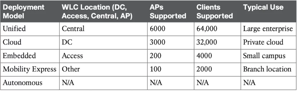
Table 27-2 shows a summary of WLC deployment models and WLC locations, and the typical maximum number of APs and clients supported by each model.
Table 27-2 Summary of WLC Deployment Models (Odom, 2020, p. 701)
The split-MAC concept can be applied to different network architectures. But where should you deploy the WLC to support multiple LAPs in your network?
The place of the WLC within the network affects how many WLCs might be needed to support the number of APs required.
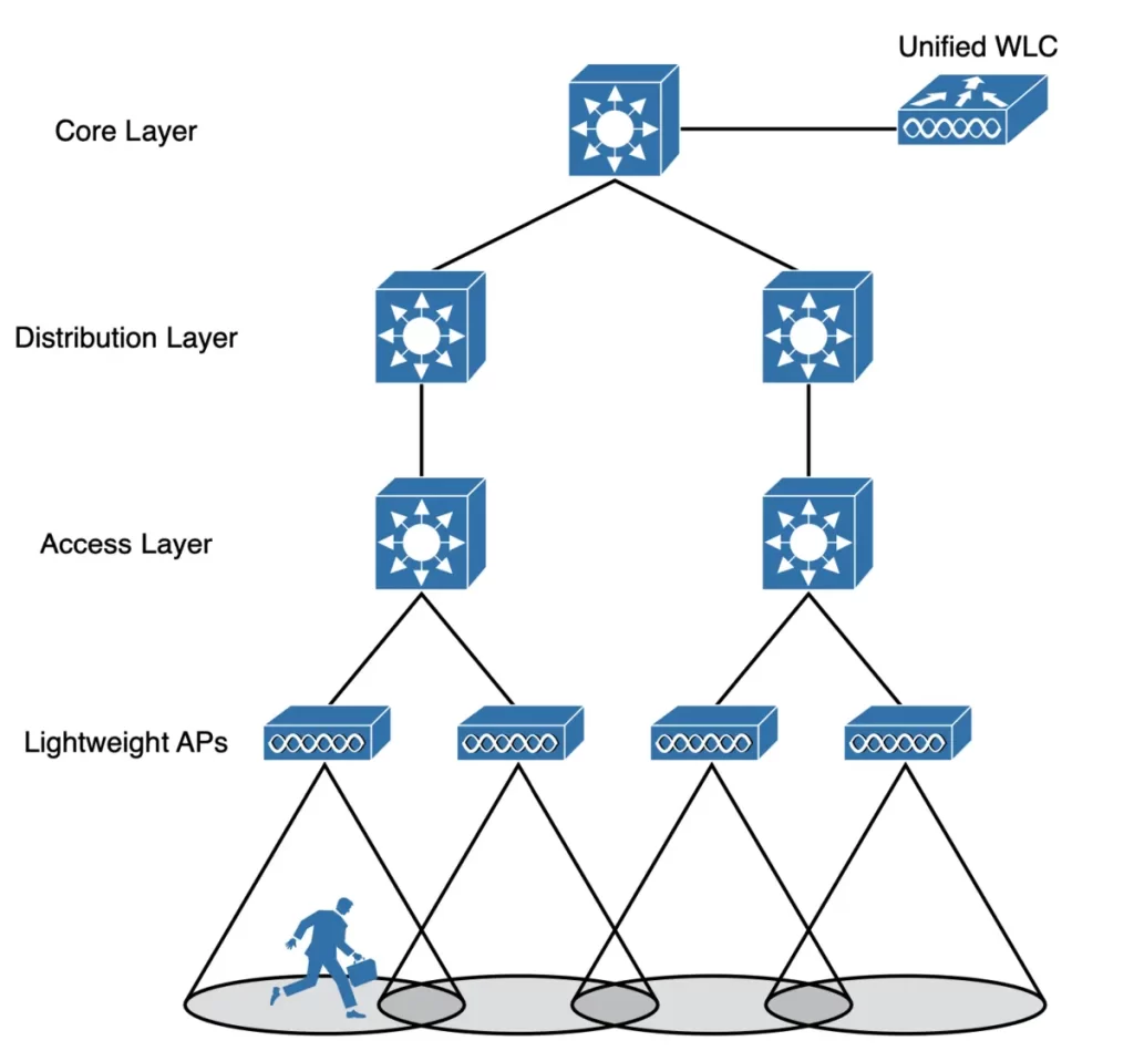
1) A unified or centralized WLC deployment corresponds to the idea that most of the resources users need to reach are located in a central location such as a data center or the Internet. Locating the WLC in a central location maximizes the number of APs joined to it, and provides a convenient place to enforce security policies that affect wireless users.
The traffic of wireless users would travel over CAPWAP tunnels that reach into the center of the network, near the core, as shown in Figure 27-8.
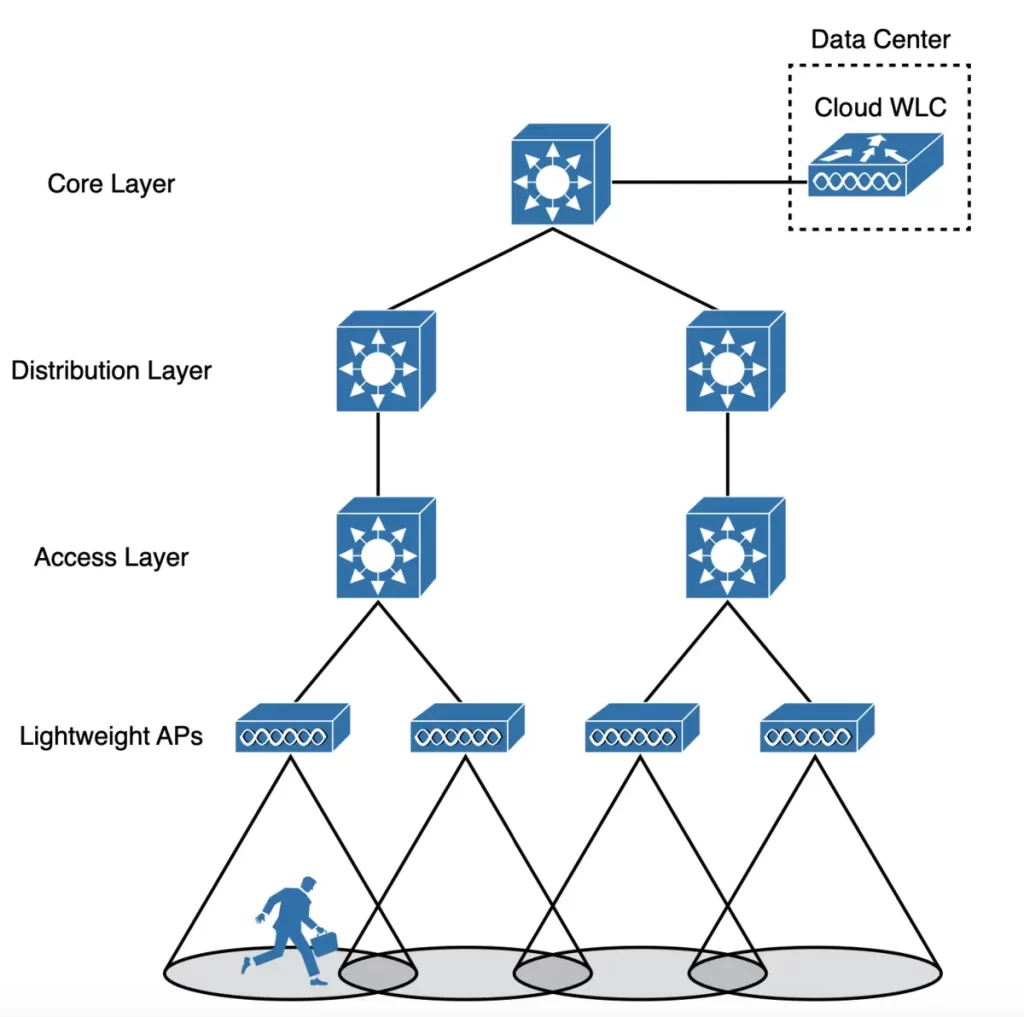
2) A cloud deployment has the WLC also located in a central position in the network, inside a data center in a private cloud, as shown in Figure 27-9. This is known as a cloud-based WLC deployment.
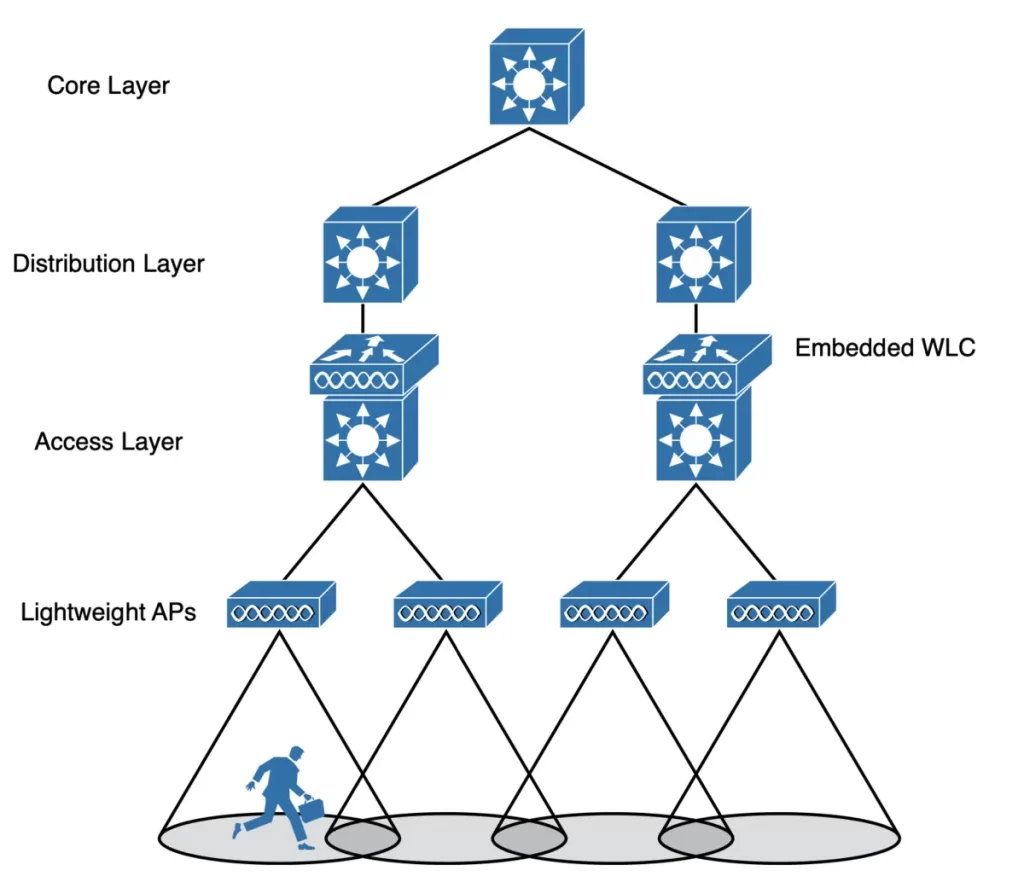
3) An embedded WLC deployment has the controller embedded within the switching hardware. This type of deployment is suitable for small campuses or distributed branch locations, where the number of APs is relatively small in each. The WLC can be co-located with a stack of switches, as shown in Figure 27-10. It is not necessary for the APs to be connected to the switches that host the WLC. APs connected to switches in other locations can join the embedded WLC.
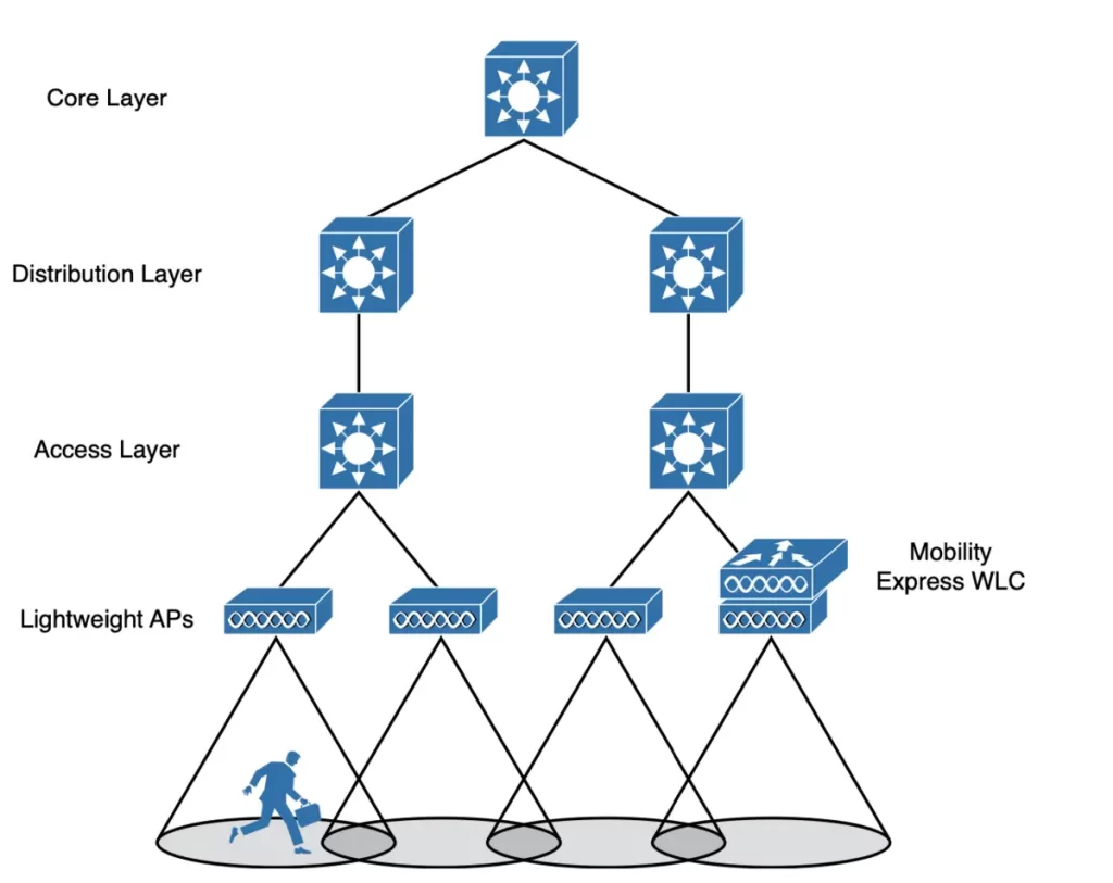
4) A Cisco Mobility Express WLC deployment, as shown in Figure 27-11. In small-scale environments, the WLC function can be co-located with an AP that is installed at the branch site, and there is no need to invest in dedicated WLCs.
The AP that hosts the WLC forms a CAPWAP tunnel with the WLC and with any other APs at the same location.
Cisco AP modes
Many Cisco APs can operate in either autonomous or lightweight mode, depending on which code image is loaded and run. From the WLC, you can also configure a lightweight AP to operate in one of the following special-purpose modes:
*Local: the default lightweight mode that offers one or more wireless networks (BSSs) on a specific channel. When the AP is not transmitting data to clients, it scans other channels to measure noise and interference, discover rogue devices, and match against IDS events.
*Monitor: the AP is not transmitting. The AP’s receiver functions as a dedicated sensor. The AP monitors for IDS events and rogue access points, and determines the position of stations through location-based services.
*FlexConnect: a FlexConnect AP at a remote site can switch traffic locally between an SSID and a VLAN even if its CAPWAP tunnel to the WLC is down, if it is configured to do so.
*Sniffer: a Cisco AP can be configured to operate in Sniffer mode, which dedicates its radios to receiving 802.11 traffic from other sources, similar to a sniffer or packet capture device. The captured traffic is then forwarded to a computer running network analyzer software such as Wireshark, where it can be further analyzed.
*Rogue detector: a Cisco AP can be configured to operate in Rogue Detector mode, where it is dedicated to detecting rogue devices by correlating MAC addresses heard on the wired network with those heard over the air. Rogue devices are those that appear on both networks.
*Bridge: a Cisco AP can be configured to operate in Bridge mode, where it becomes a dedicated bridge (point-to-point or point-to-multipoint) between two networks. Two APs in Bridge mode can be used to link two locations separated by a distance, and multiple APs in Bridge mode can form an indoor or outdoor mesh network.
*Flex+Bridge: FlexConnect operation is enabled on a mesh AP.
*SE-Connect: in SE-Connect mode, a Cisco AP dedicates its radios to analyzing the spectrum on all wireless channels. You can remotely connect a computer running software such as MetaGeek Chanalyzer or Cisco Spectrum Expert to the AP to collect and analyze the spectrum analysis data to identify sources of interference.
A LAP is normally in local mode when it is providing BSSs and allowing client devices to associate to wireless LANs. If configured to operate in one of the other modes, an AP’s local mode (and the BSSs) is disabled.
Practice quiz questions
You can find four quiz questions and answers for this lesson in Odom, 2020, pp. 686-690.
Key references
Odom, W. (2020). Chapter 27. Analyzing Cisco Wireless Architectures, CCNA 200-301 Official Cert Guide (pp. 686-702), Volume 1. Cisco Press.
Related content
Compliance frameworks and industry standards
Configure WLAN within the GUI using WPA2 PSK
How data flow through the Internet
How to break into information security
IT career paths – everything you need to know
Job roles in IT and cybersecurity
The GRC approach to managing cybersecurity
The Security Operations Center (SOC) career path
Wireless fundamentals for the CCNA
Back to DTI Courses


