This lesson constitutes Part 4 of 4 of the wireless networking series of lessons for the CCNA. This lesson explains how to configure and verify WLAN within the GUI using WPA2 PSK. Part 1, Wireless fundamentals for the CCNA, introduced key wireless networking concepts such as access point (AP), basic service set (BSS), extended service set (ESS), and Service Set Identifier (SSID), in addition to discussing the importance of IEEE 802.11 for wireless design and deployment. Part 2, Cisco wireless architectures and AP modes, compared Cisco wireless architectures and AP modes, focusing on network design aspects related to scalability, management, and deployment. Part 3, Wireless network security, examined various methods for securing a wireless network, covering a lot of authentication methods and encryption and message integrity algorithms. Now we are ready to configure a wireless LAN with effective security.
This lesson has two main objectives. First, apply the knowledge accumulated from parts 1-3 toward understanding how to build a functioning network with APs and a WLC. Second, based on the concepts covered in Part 3, Wireless network security, learn how to configure the WLAN to use WPA2-Personal. Specifically, this lesson focuses on the following sections and topics of the CCNA exam topics list. First, Section 2, Network Access, subsection 2.7 Describe physical infrastructure connections of WLAN components (AP, WLC, access/trunk ports, and LAG), subsection 2.8 Describe AP and WLC management access connections (Telnet, SSH, HTTP, HTTPS, console, and TACACS+/RADIUS), and subsection 2.9 Interpret the wireless LAN GUI configuration for client connectivity, such as WLAN creation, security settings, QoS profiles, and advanced settings. Second, Section 5, Security Fundamentals, subsection 5.10 Configure and verify WLAN within the GUI using WPA2 PSK. This post constitutes Issue 44 of my CCNA 200-301 study notes.
- Connecting a Cisco AP
- Accessing a Cisco WLC
- Connecting a Cisco WLC
- Using WLC ports
- Using WLC interfaces
- Configuring a WLAN
- Step 1. Configure a RADIUS server
- Step 2. Create a dynamic interface
- Step 3. Create a new WLAN
- Configuring WLAN security
- Configuring WLAN QoS
- Configuring advanced WLAN settings
- Finalizing WLAN configuration
- Practice quiz questions
- Key references
You may also be interested in CCNA wireless networking portal.
Connecting a Cisco AP
This section discusses connecting the wired side of APs to the network infrastructure so that the APs can pass traffic between the appropriate VLANs and WLANs.
Recall, in the case of a wireless network architecture using lightweight APs, the APs are coupled with one or more wireless LAN controllers (WLCs).
Recall, autonomous APs are self-contained devices that can be configured and managed independently. They do not require a WLC. Nothing else is needed to move Ethernet frames between wired VLAN and WLAN. The AP maps each VLAN to a WLAN and BSS.
Since the autonomous AP has a single wired Ethernet interface (see Figure 29-1), multiple VLANs must be connected to it via a trunk link.
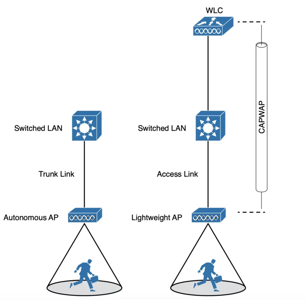
A lightweight AP also has a single wired Ethernet interface. However, lightweight APs are managed and configured by a WLC. They do not have their own operating system or management interface.
Multiple wired VLANs extending from the WLC to the AP are carried over the CAPWAP tunnel between the WLC to the AP where the VLANs can be mapped to WLANs that emerge at the AP. So the AP needs only an access link to connect to the network infrastructure and terminate its end of the tunnel.
NOTE – A switch port providing a wired connection to an AP must be configured to support either access or trunk mode. In trunk mode, 802.1Q encapsulation tags each frame according to the VLAN number it came from. The wireless side of an AP inherently trunks 802.11 frames by marking them with the BSSID of the WLAN where they belong. (Odom, 2020, p. 722)
To configure and manage Cisco APs, you can connect a serial console cable from your computer to the AP’s console port. Once the AP is up and running and has an IP address, you can also use Telnet or SSH to connect to its CLI over the wired network.
How autonomous APs and lightweight APs are managed:
Autonomous APs can be managed using a web browser over HTTP or HTTPS. To do this, you will need to connect to the AP’s IP address using a web browser. Once you are connected, you will be able to access the AP’s management interface. The management interface will allow you to configure the AP’s settings, such as the SSID, security settings, and wireless channels.
Lightweight APs can be managed from a browser session to the WLC. To do this, you will need to connect to the WLC’s IP address using a web browser. Once you are connected, you will be able to access the WLC’s management interface. The management interface will allow you to configure the WLC’s settings, such as the WLANs, security settings, and wireless channels. You can also use the WLC’s management interface to manage the lightweight APs that are connected to it.
Accessing a Cisco WLC
After the WLC has an initial configuration and a management IP address assigned to its management interface, you can connect and configure the WLC using a web browser opened to the WLC’s management address with either HTTP or HTTPS.
How to do the WLC initial configuration is beyond the scope of the CCNA, but if you are curious about how to do it: How to build a WLAN and configure it using the GUI of the WLC.
Using the graphical user interface (GUI) is an effective method to monitor, configure, and troubleshoot a wireless network.
You can also connect to a WLC using a secure shell (SSH) session. Once connected, you can use the WLC’s CLI to monitor, configure, and debug activity on the WLC and the wireless network it manages.
To access the web-based GUI or the CLI, management users must log in. Users can be authenticated against a local user database or against an external authentication, authorization, and accounting (AAA) server, such as TACACS+ (Terminal Access Controller Access Control System Plus) or RADIUS (Remote Authentication Dial-In User Service).
A TACACS+ server is a software application that implements the TACACS+ protocol. Similarly, a RADIUS server is a software application that implements the RADIUS protocol.
TACACS+ is a Cisco-developed secure protocol used for centralized authentication, authorization, and accounting (AAA) in network devices. It uses a client-server architecture where the network device (client) communicates with a TACACS+ server for user verification and access control. RADIUS is another popular AAA protocol that also implements a client-server architecture for centralized AAA management, but it is not developed by Cisco.
TACACS+ offers several advantages over RADIUS, such as:
- Enhanced security: TACACS+ uses TCP for reliable communication and encrypts all data exchange.
- Granular control: TACACS+ allows for more granular control over user access and privileges.
- Scalability: TACACS+ can be easily scaled to support a large number of users and devices.
To start setting the WLC, open a web browser to the WLC management address, look for the initial login screen and Login button, then enter your user credentials as you are prompted for them.
After logging in, you will see a dashboard similar to the one shown in Figure 29-3. To start making configurations, click on the Advanced button (in the upper-right corner). This should bring up the full WLC GUI, as shown in Figure 29-4.
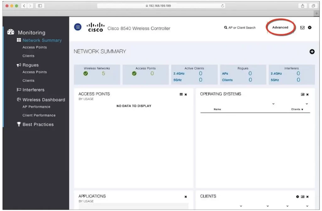
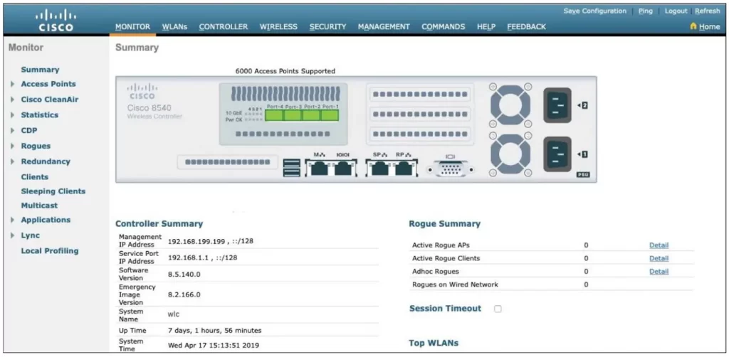
The vertical list of functions at the left side of the screen changes according to the selected tab across the top of the screen. You can expand the list entries. The main screen area displays the relevant fields and options to edit as you make configuration changes.
Shortly, we will look at which tabs and list items we should use to configure the WLC.
Connecting a Cisco WLC
To connect a Cisco WLAN controller to the network we first need to be familiar with the different types of connections.
While in Cisco routers and switches the terms interface and port are usually interchangeable, in Cisco wireless controllers ports and interfaces refer to different concepts.
Controller ports are physical connections made to an external wired or switched network, whereas interfaces are logical connections made internally within the controller. (Odom, 2020, p. 726)
Let’s look at each connection type in more detail.
Using WLC ports
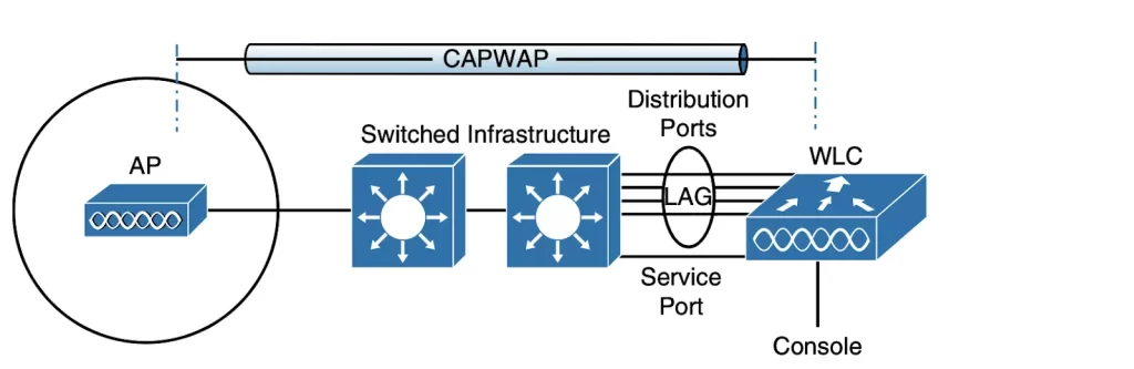
Several types of controller ports can be connected to a network (see Figure 29-5):
■ Service port: used for managing the WLC out-of-band, recovering the system, and performing initial boot functions; always connected to a switch port in access mode.
■ Distribution system port: used for all normal AP and management traffic; usually connects to a switch port in 802.1Q trunk mode.
■ Console port: used for out-of-band management, system recovery, and initial boot functions; asynchronous connection to a terminal emulator (9600 baud, 8 data bits, 1 stop bit, by default).
■ Redundancy port: used to connect to a peer controller for high availability (HA) operation.
WLCs typically have a single service port that connects to a switched network. The service port is typically assigned to a management VLAN so that you can access the WLC using SSH or a web browser to perform initial configuration or maintenance. The switch port corresponding to the service port must be configured for access mode only because the service port supports only a single VLAN
WLCs typically have multiple distribution system ports that must be connected to the network. These ports carry most of the data that goes to and from the WLC. For example, CAPWAP tunnels (control and data) that extend to each of the WLC’s APs pass across the distribution system ports. Client data also uses the ports to travel from wireless LANs to wired VLANs. In addition, any management traffic, such as that from a web browser, SSH, Simple Network Management Protocol (SNMP), Trivial File Transfer Protocol (TFTP), and so on, normally reaches the WLC in-band through the ports.
Distribution system ports carry data from many different VLANs. For this reason, distribution system ports always operate in 802.1Q trunking mode. When connecting distribution system ports to a switch, you should also configure the switch ports for unconditional 802.1Q trunk mode.
Distribution system ports can work independently, each one carrying multiple VLANs to a unique group of internal controller interfaces. You can configure distribution system ports in redundant pairs to achieve resiliency. One port is used as the primary port, and the other port is used as the backup port.
To maximize the bandwidth of each distribution system port, you can configure them to work together as a single logical group, similar to an EtherChannel or port-channel on a switch.
Controller distribution system ports can be configured as a link aggregation group (LAG) such that they are bundled together to act as one larger link. In Figure 29-5, the four distribution system ports are configured as a LAG. With a LAG configuration, traffic can be load-balanced across the individual ports that make up the LAG. In addition, LAG offers resiliency; if one individual port fails, traffic will be redirected to the remaining working ports instead. (p. 727)
While the LAG acts as a traditional EtherChannel, Cisco WLCs do not support any link aggregation negotiation protocol, such as LACP or PAgP. So switch ports must be configured as an unconditional or always-on EtherChannel.
Using WLC interfaces
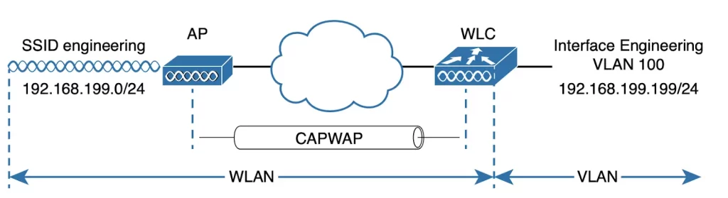
A WLC can connect to multiple VLANs on the switched network through its distribution system ports. Internally, the WLC must map those wired VLANs to equivalent logical wireless networks. For example, if VLAN 10 is set aside for wireless users in the Engineering division of a company, the WLC must connect that VLAN to a unique wireless LAN that exists on the WLC and its associated APs. The wireless LAN must then be extended to each client that associates with the SSID “Engineering.”
Cisco wireless controllers provide connectivity through internal logical interfaces. These interfaces must be configured with an IP address, subnet mask, default gateway, and DHCP server. Each interface is then assigned to a physical port and a VLAN ID. An interface can be thought of as a Layer 3 termination on a VLAN.
Cisco controllers support the following interface types (shown in Figure 29-6).
■ Dynamic interface: connects a VLAN to a WLAN. Dynamic interfaces are used to map WLANs to VLANs, creating logical connections between wireless and wired networks. Each WLAN is mapped to a dynamic interface, which is configured with its own IP address. Dynamic interfaces can also act as DHCP relays for wireless clients, and can be configured with access lists to filter traffic.
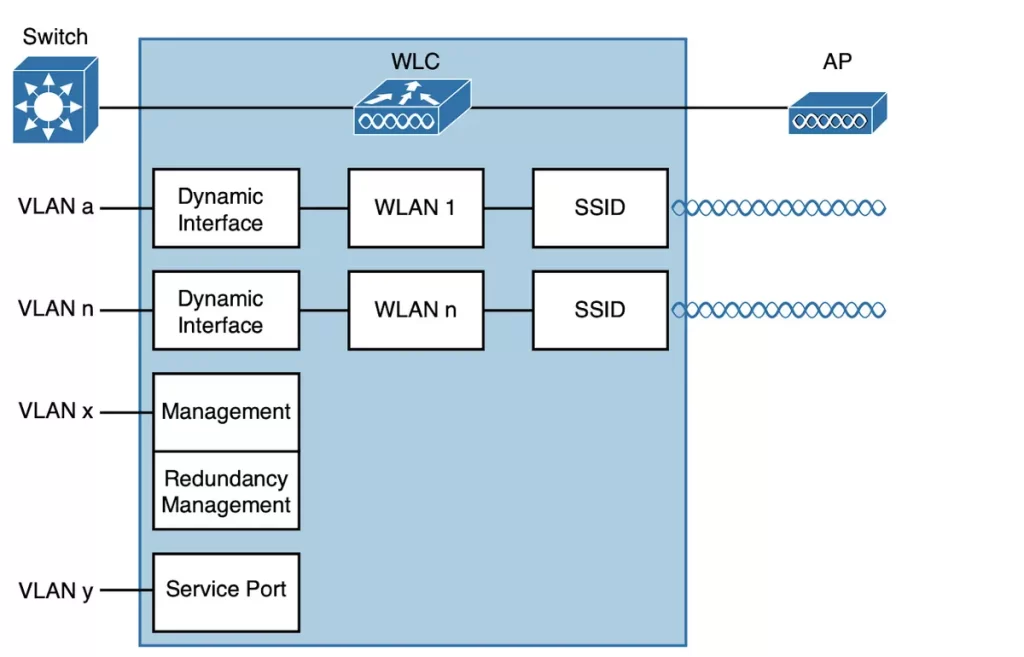
■ Virtual interface: IP address used only for certain client management functions, when the controller is relaying client DHCP requests, performing client web authentication, and supporting client mobility.
When a wireless client issues a request to obtain an IP address, the controller can relay the request on to an actual DHCP server to obtain an IP address. From the viewpoint of clients, “the DHCP server appears to be the controller’s virtual interface address. Clients may see the virtual interface’s address, but that address is never used when the controller communicates with other devices on the switched network” (p. 728).
Configure the virtual interface with a unique, non-routable address. For example, you might use 10.1.1.1 because it is within a private address space defined in RFC 1918. Or use an IP address from the RFC 1918 private address space that is unused or reserved, such as 192.168.1.1. You could also use a reserved address from RFC 5737 (192.0.2.0/24) that is set aside for documentation purposes and is never used.
To support client mobility, controllers in the same mobility group should be configured with the same virtual address, so all the controllers will appear to operate as a cluster as clients roam from controller to controller.
■ Management interface: faces the switched network, where management users and APs are located. Used for normal management traffic, such as RADIUS user authentication using protocols like HTTPS, SSH, SNMP, NTP, and TFTP. Management interface traffic also consists of CAPWAP packets that carry control and data tunnels to and from the APs.
■ Redundancy management: the management IP address of a redundant WLC. The active WLC uses the management interface address, while the secondary WLC uses the redundancy management address.
■ Service port interface: bound to the service port and used for out-of-band management.
Configuring a WLAN
Let’s look at how to configure WLAN ports and interfaces via the WLC GUI.
In a wireless network (we are focusing on the lightweight AP architecture) the AP advertises a SSID for a client to join, and the controller connects to a VLAN through one of its dynamic interfaces. To complete the path between the SSID and the VLAN, we must first define a WLAN on the controller. Figure 29-7 presents a WLAN example using the WPA2-Personal (PSK) security model.
The WLC binds the WLAN to one of its interfaces. The WLAN configuration is then pushed out to the APs. Subsequently, wireless clients learn about a new WLAN by receiving its beacons and can then probe and join the new BSS.
WLANs can segregate wireless users and their traffic into logical networks. Traffic can be routed from one WLAN to another by routing traffic from one VLAN to another through the wired network infrastructure.
You might be tempted to create many WLANs, e.g., to keep groups of users separate. But as a rule of thumb, always limit the number of WLANs to five or fewer. A maximum of three WLANs is ideal. Cisco controllers can support a maximum of 512 WLANs, but only 16 of them can be actively configured on an AP. Advertising each WLAN to potential wireless clients consumes valuable airtime.
Every AP must broadcast beacon management frames at regular intervals to advertise the existence of a BSS. Because each WLAN is bound to a BSS, each WLAN must be advertised with its own beacons. Beacons are normally sent 10 times per second, or once every 100 ms, at the lowest mandatory data rate. The more WLANs you have created, the more beacons you will need to announce them. (p. 730)
Creating too many WLANs can starve a channel of any usable airtime. Clients will have difficulty transmitting their own data because the channel is busy with beacon transmissions coming from the AP.
A controller by default has a limited initial configuration. No WLANs are defined out-of-the-box.
Before you create a new WLAN, think about the following parameters it will need to have:
■ SSID string
■ Controller interface and VLAN number
■ Type of wireless security needed
As we walk through the WLAN configuration steps, we will learn how to create the appropriate dynamic controller interface to support the new WLAN and how to enter the necessary WLAN parameters.
Each configuration step is performed using a web browser session that is connected to the WLC’s management IP address.
Step 1. Configure a RADIUS server
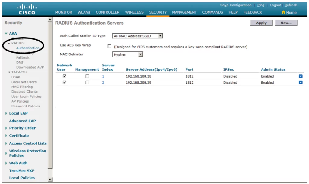
First, define your server if your security settings require a RADIUS server such as WPA2-Enterprise or WPA3-Enterprise. Select Security > AAA > RADIUS > Authentication. Now you should be able to see a list of servers that are already configured (see Figure 29-8). Notice, the controller already has two RADIUS servers configured.
Click New to create a new server. If multiple servers are defined, the controller will try them sequentially.
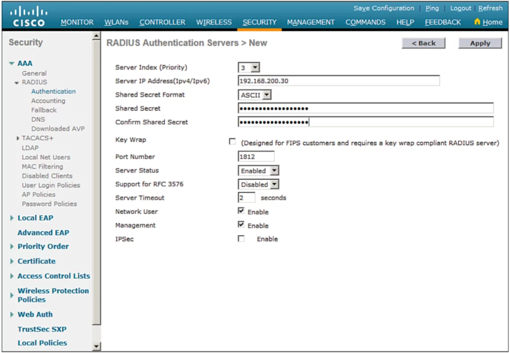
Next enter the server parameters as shown in Figure 29-9. Click Apply to complete the server configuration.
Step 2. Create a dynamic interface
A dynamic interface connects the controller to a VLAN on the wired network. Creating a WLAN binds the dynamic interface (and VLAN) to a wireless network.
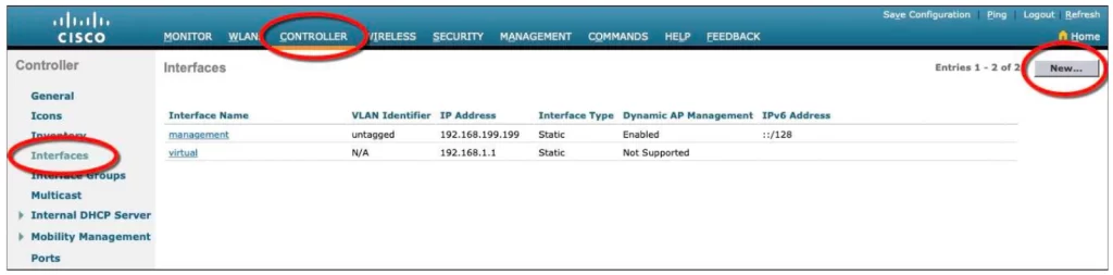
Navigate to Controller > Interfaces. Notice in our example in Figure 29-10, you can see two interfaces named “management” and “virtual” are already configured. Click the New button to define a new interface.
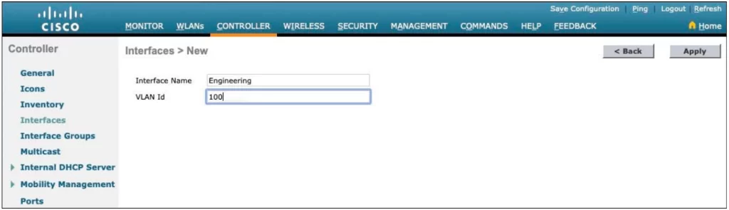
Enter a name for the interface and the VLAN number it will be bound to. For example, in Figure 29-11 the interface Engineering will map to wired VLAN 100. Click the Apply button.
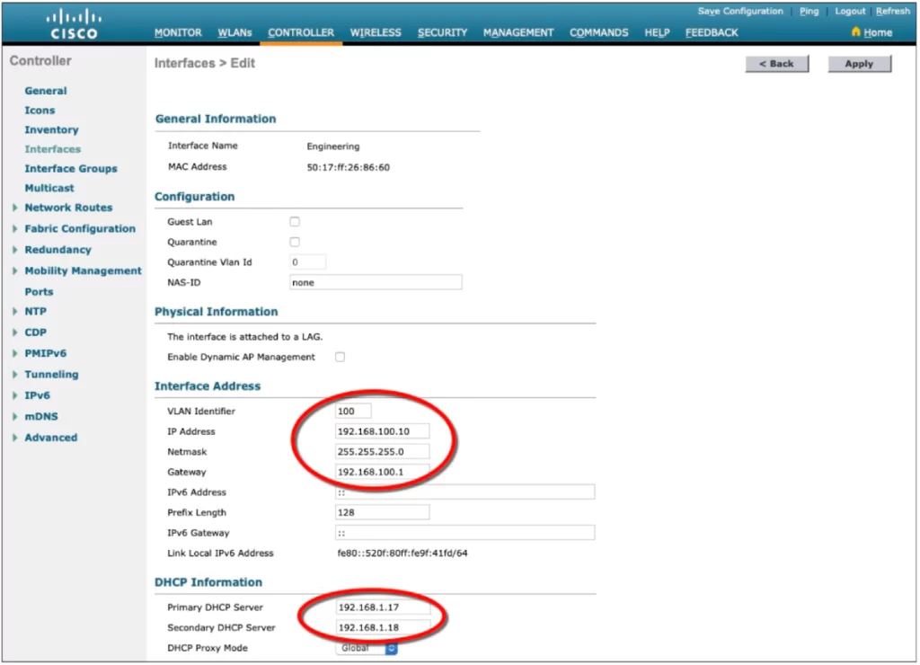
Next, supply the IP address, subnet mask, and gateway address for the interface; define primary and secondary DHCP server addresses the WLC will use to relay DHCP requests from clients that are bound to the interface (see Figure 29-12).
Click the Apply button to complete the interface configuration and go back to the list of interfaces.
Step 3. Create a new WLAN
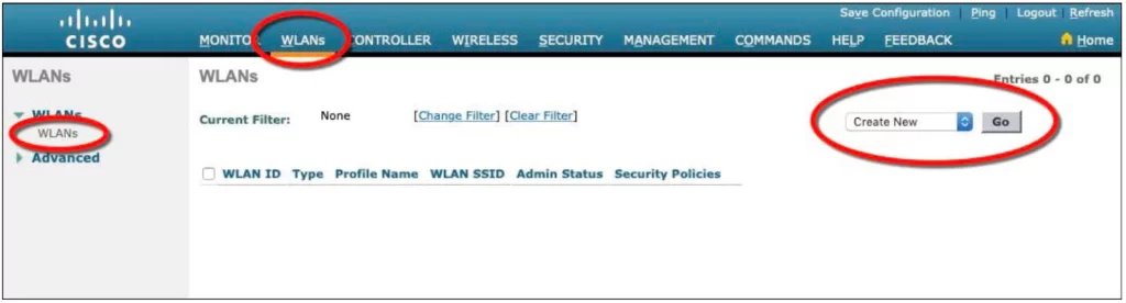
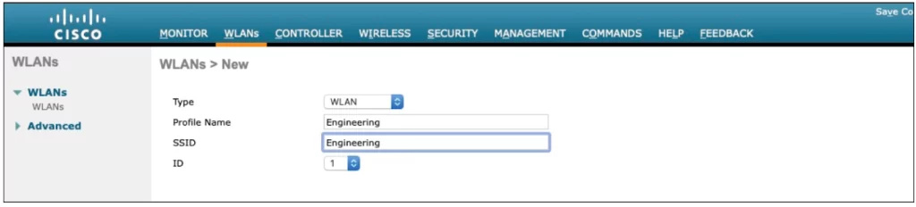
The controller in Figure 29-13 does not have any WLANs already defined. Create a new WLAN by selecting Create New from the drop-down menu and then clicking the Go button.
Next, enter a descriptive name for the new WLAN profile. In Figure 29-14, the admin used Engineering for both the profile name and SSID.
The WLAN ID number, 1 in our illustration, becomes useful when you use templates in Prime Infrastructure (PI) to configure WLANs on multiple controllers at the same time.
NOTE – WLAN templates are applied to specific WLAN ID numbers on controllers. The WLAN ID is only locally significant and is not passed between controllers. As a rule, you should keep the sequence of WLAN names and IDs consistent across multiple controllers so that any configuration templates you use in the future will be applied to the same WLANs on each controller. (p. 734)
Click Apply to create the new WLAN. Now you move to a page where you can edit four categories of parameters, corresponding to the tabs across the top as shown in Figure 29-15.
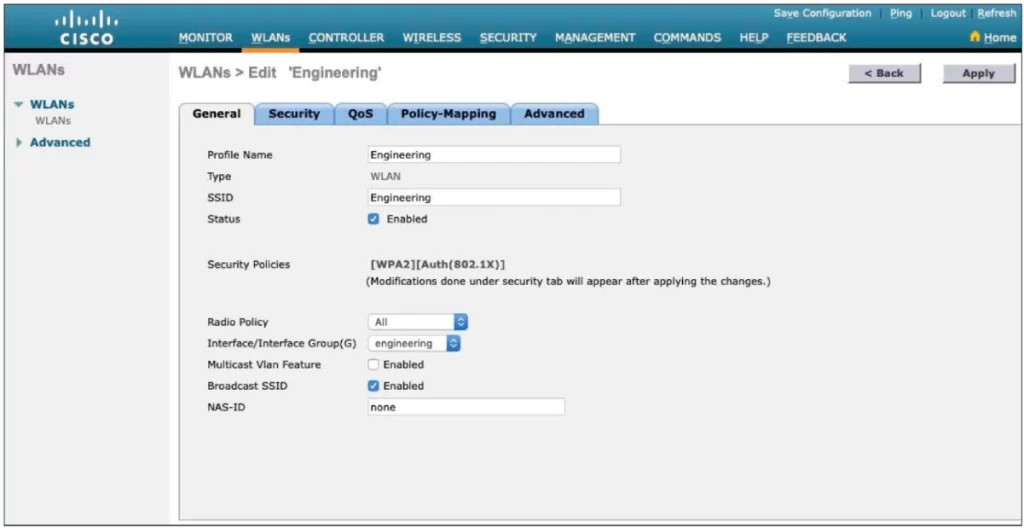
From the General tab, checking the Status box enables the WLAN. You can change the default security policy showing (WPA2 with 802.1x) through the Security tab.
Next, set Radio Policy. Select the type of radio that will offer the WLAN. All is selected by default, meaning the WLAN will be offered on all radios joined with the controller.
You can select a more specific policy with 802.11a only, 802.11a/g only, 802.11g only, or 802.11b/g only. For example, if you are creating a new WLAN for devices that have only a 2.4-GHz radio, it probably does not make sense to advertise the WLAN on both 2.4- and 5-GHz AP radios. (p. 734)
Next, select the dynamic interface that will be bound to the WLAN from the drop-down menu. The management interface is selected by default.
Finally, check the Broadcast SSID box to instruct the APs to broadcast the SSID name in the beacons they transmit.
Configuring WLAN security
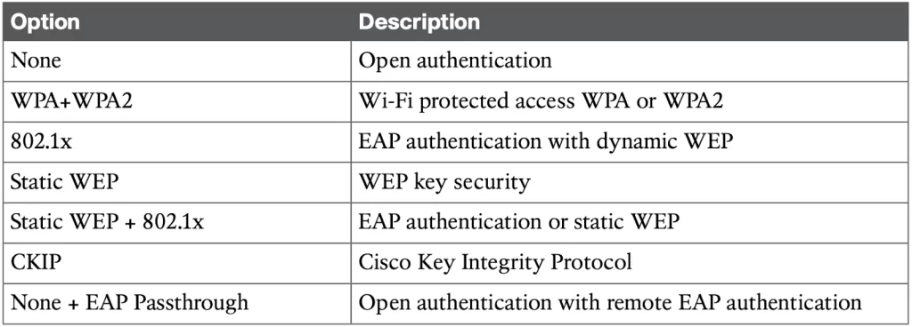
Configure the security settings from the Security tab (see Figure 29-16). The Layer 2 Security tab is selected by default. From the drop-down menu, select the appropriate security scheme. Table 29-2 lists the types of security schemes available.
Table 29-2 Layer 2 WLAN Security Type (p. 735)
Moving down the screen (Figure 29-16), select which specific WPA, WPA2, and WPA3 methods to support on the WLAN. You can select more than one.
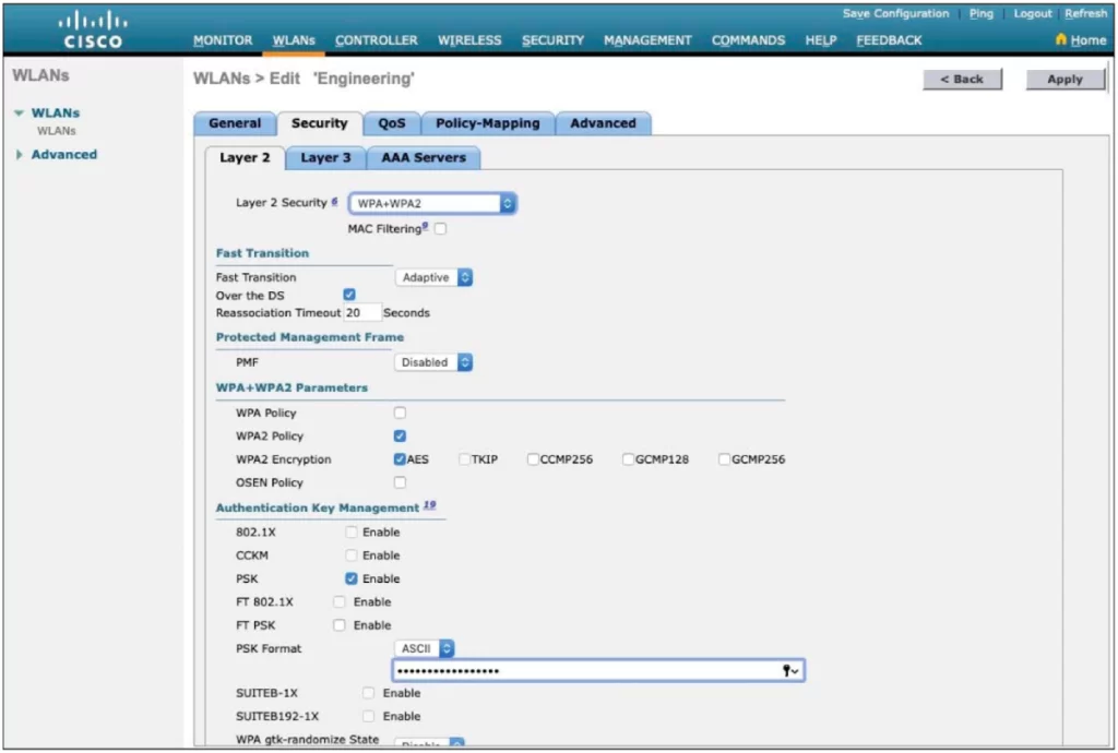
In Figure 29-16, select the authentication methods the WLAN should use from under the Authentication Key Management section. Only PSK has been selected so the WLAN will only allow WPA2-Personal with pre-shared key authentication.
WPA2-Enterprise and WPA2-Personal are considered two different protocols. They both use the same encryption method, but they use different authentication methods.
WPA2-Personal uses a pre-shared key (PSK), which is a passphrase that is shared between all devices that connect to the network. The PSK is used to authenticate devices and encrypt data.
WPA2-Enterprise uses an authentication server, such as a RADIUS server, to authenticate devices. The authentication server verifies the user’s identity and then issues a temporary key to the device. The temporary key is used to encrypt data.
WPA2-Enterprise is considered to be more secure than WPA2-Personal because it uses an authentication server to verify the user’s identity. This makes it more difficult for unauthorized users to gain access to the network.
To use WPA2-Enterprise, select the option 802.1X. In which case, 802.1x and EAP would be used to authenticate wireless clients against one or more RADIUS servers. The controller would use servers from the global list defined under Security > AAA > RADIUS > Authentication.
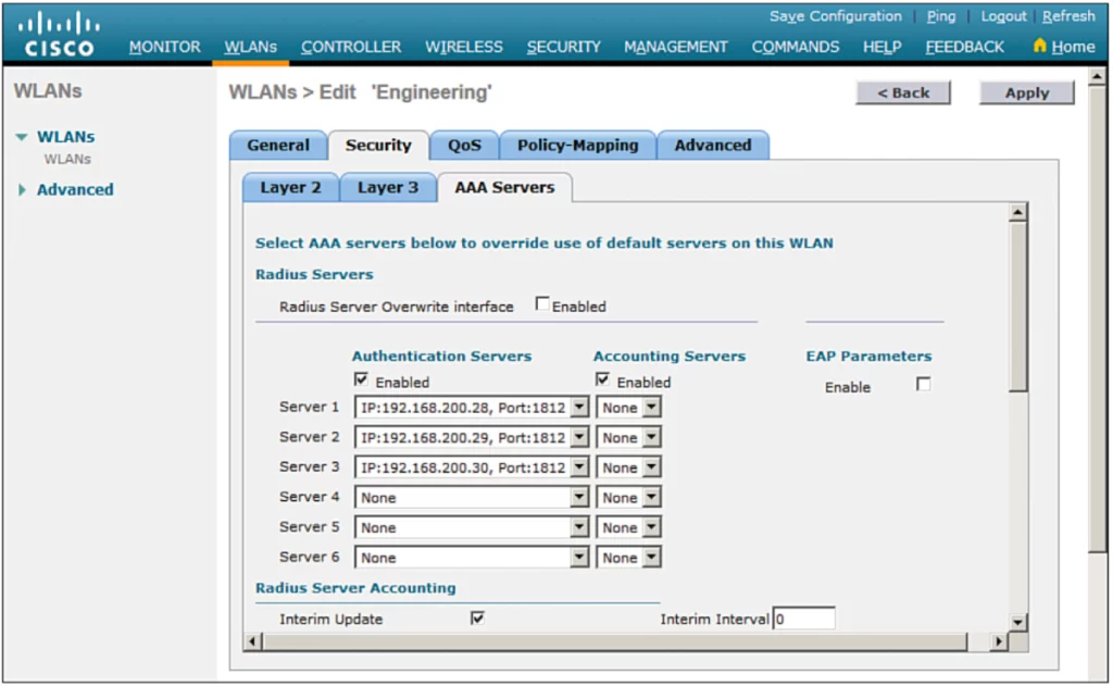
To specify the servers the WLAN should use, select the Security tab and then the AAA Servers tab in the WLAN edit screen.
You can identify up to six specific RADIUS servers in the WLAN configuration. Beside each server, select a specific server IP address from the drop-down menu of globally defined servers. The servers are tried in sequential order until one of them responds. (p. 736)
Figure 29-17 shows what a WLAN configured for WPA2-Enterprise might look like.
By default, a RADIUS server will be contacted by a controller from its management interface. You can override this behavior by checking the box next to Radius Server Overwrite Interface so that the controller sources RADIUS requests from the dynamic interface that is associated with the WLAN.
Configuring WLAN QoS
Select the QoS tab (see Figure 29-18).
By default, the controller will handle all frames in the WLAN in a “best effort” manner. You can select the Quality of Service (QoS) to classify all frames using the drop-down menu:
■ Platinum (voice)
■ Gold (video)
■ Silver (best effort)
■ Bronze (background)
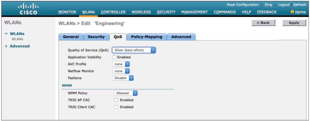
On the same QoS page, you can set the Wi-Fi Multimedia (WMM) policy, call admission control (CAC) policies, and bandwidth parameters.
Configuring advanced WLAN settings
The Advanced tab allows you to configure a variety of advanced WLAN settings (see Figure 29-19).
Most of the advanced settings are beyond the scope of the CCNA objectives, but you should be aware of a few defaults that might affect your wireless clients.
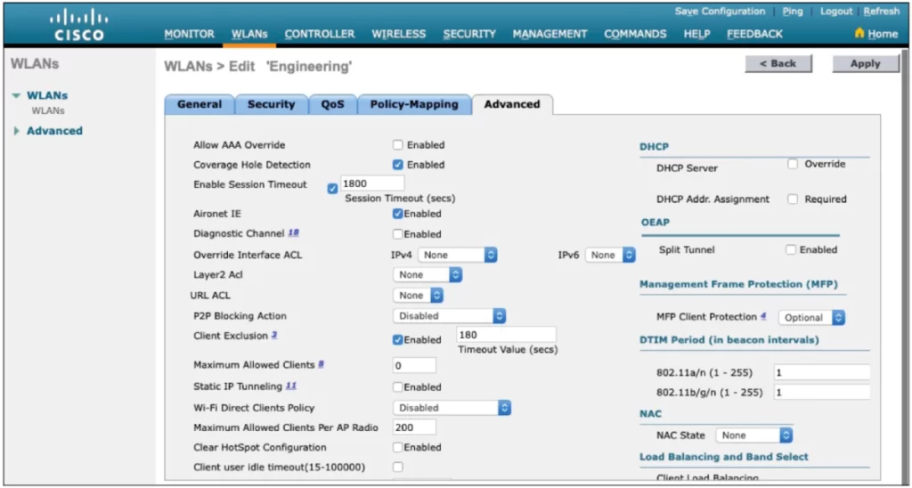
*Client sessions with the WLAN are capped at 1800 seconds (30 minutes) by default. A client will be required to reauthenticate after the session expires.
*A controller maintains a set of security policies used to detect potentially malicious wireless clients. If a client exhibits a certain behavior, the controller can exclude a client from the WLAN for a period of time if the client displays a certain behavior.
*Note, all clients are subject to the security policies configured under Security > Wireless Protection Policies > Client Exclusion Policies.
These policies include excessive 802.11 association failures, 802.11 authentication failures, 802.1x authentication failures, web authentication failures, and IP address theft or reuse. Offending clients will be automatically excluded or blocked for 60 seconds, as a deterrent to attacks on the wireless network. (p. 738)
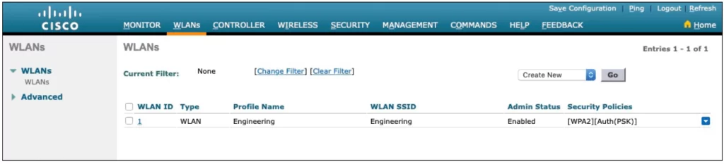
Finalizing WLAN configuration
Click the Apply button in the upper-right corner of the WLAN Edit screen to finalize the configurations. This will create the WLAN and add it to the controller configuration. In Figure 29-20, the Engineering WLAN has been added as WLAN ID 1 and is enabled for use.
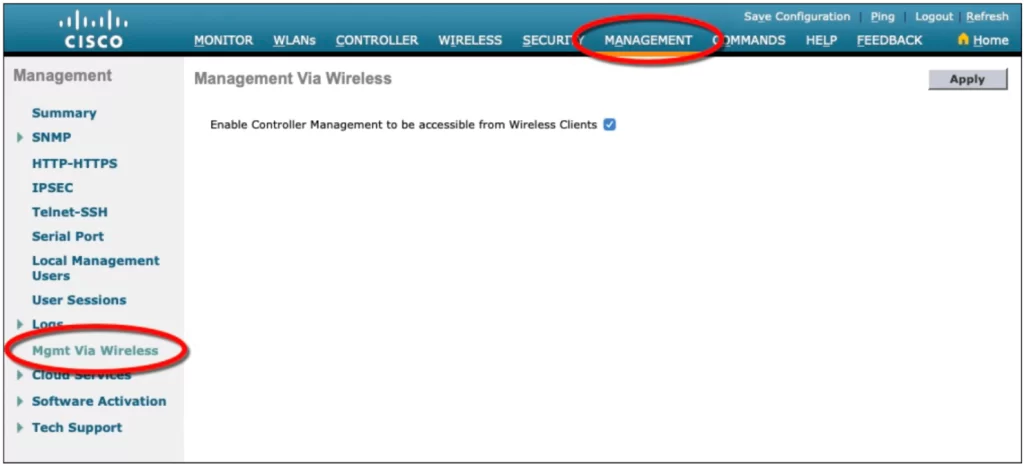
Note that a controller will not permit management traffic initiated from a WLAN. This way, “the controller is kept isolated from networks that might be easily accessible or where someone might eavesdrop on the management session traffic” (p. 739).
*You can change the default behavior on a global basis (all WLANs) by selecting the Management tab and then selecting Mgmt Via Wireless, as shown in Figure 29-21. Check the box to allow management sessions from any WLAN that is configured on the controller. (p. 739)
Practice quiz questions
You can find four quiz questions and answers for this lesson in Odom, 2020, pp. 720-724.
Key references
Odom, W. (2020). Chapter 29. Building a Wireless LAN, CCNA 200-301 Official Cert Guide (pp. 720-740), Volume 1. Cisco Press.
Related content
Cisco wireless architectures and AP modes
Compliance frameworks and industry standards
How data flow through the Internet
How to break into information security
IT career paths – everything you need to know
Job roles in IT and cybersecurity
The GRC approach to managing cybersecurity
The Security Operations Center (SOC) career path
Wireless fundamentals for the CCNA
Back to DTI Courses


