This lesson discusses wireless fundamentals for the CCNA. This is Part 1 of 4 of wireless networking study notes for the CCNA. This lesson introduces the architecture and key components of a wireless network and how the network is organized in terms of structure and function to control access to the wireless medium and allow devices to exchange data. We learn about how a single access point (AP) can provide a basic service set (BSS) for a cell area, and how multiple APs can be connected to form an extended service set (ESS) for a larger network.
Part 2, Cisco wireless architectures and AP modes, compares Cisco wireless architectures and AP modes, focusing on network design aspects related to scalability, management, and deployment. Part 3, Wireless network security, examines various methods for securing a wireless network, covering a lot of authentication methods and encryption and message integrity algorithms. Part 4, Configure WLAN within the GUI using WPA2 PSK, explains how to configure and verify WLAN within the GUI using WPA2 PSK.
This lesson, Wireless fundamentals for the CCNA, focuses on the following exam topics in Section 1, Network Fundamentals, of the CCNA exam blueprint: the role and function of Access Points (1.1.d), and wireless principles relating to Nonoverlapping Wi-Fi channels (1.11.a), SSID (1.11.b), and RF (1.11.c). This post constitutes Issue 41 of my CCNA 200-301 study notes.
- Comparing wired and wireless networks
- Wireless LAN topologies
- Basic Service Set (BSS)
- Distribution System (DS)
- Extended Service Set (ESS)
- Independent Basic Service Set (IBSS)
- Other wireless topologies
- Repeater
- Workgroup Bridge (WGB)
- Outdoor Bridge
- Mesh Network
- RF (radio frequency) overview
- Wireless bands and channels
- APs and wireless standards
- Practice quiz questions
- Key references
You may also be interested in CCNA wireless networking portal.
Comparing wired and wireless networks
In a wired network, data that passes over the wire is bounded by the physical properties of the wire. IEEE 802.3 set of standards defines strict guidelines for the Ethernet wire specifications. “Even the type and size of the wire strands, the number of twists the strands must make around each other over a distance, and the maximum length of the wire must adhere to the standard” (Odom, 2020, p. 666).
IEEE 802.3 also defines strict guidelines for how devices can connect, send, and receive data over the wire. “Wired connections have been engineered with tight constraints and have few variables that might prevent successful communication” (p. 666).
But wired networks have some shortcomings. When a device is connected by a wire, it cannot move easily or very far. As devices get smaller and more mobile, connecting them to a physical wire ceases to be practical.
Wireless LANs transmit signals over radio frequencies (RFs) to move data from one device to another. Transmitters and receivers can be fixed in consistent locations or they can be mobile.
A wireless network eliminates “the need to be tethered to a wire or cable” offering convenience and mobility by enabling users to move around freely while staying connected to the network. A user’s various wireless devices can connect to the network easily and seamlessly.
Wireless communication offers benefits but also introduces variables that might impact successful network management. While wireless data travels in the air without the constraints of a wire, the tradeoff for this benefit is losing the protection of the wire and the control physical wiring can provide.
In the free space environment, many variables can affect the data and its delivery. To minimize the variables, wireless engineering efforts must focus on two things:
- Wireless devices must adhere to a common standard (IEEE 802.11).
- Wireless coverage must exist in the area where devices are expected to use it.
Wireless LAN topologies
Wireless communication takes place over free space through the use of radio frequency (RF) signals. A basic setup of wireless communication involves a transmitter sending RF signals to a receiver. The two devices can communicate with each other at any and all times as long as both devices are tuned to the same frequency (or channel) and support the same rules (set of standards) to carry the data between them.
The bigger the number of wireless devices simultaneously transmitting signals, the more likely is interference to happen. Multiple signals received simultaneously by a device can interfere with each other.
In a traditional (nonswitched) Ethernet LAN multiple hosts can connect to a shared media and share a common bandwidth. The hosts must operate at half duplex, either sending or receiving data at any one time, to avoid colliding with other transmissions already in progress.
A wireless LAN is similar. Because multiple devices can use the same wireless channel, they also share the same “airtime” or access to that channel. To avoid collisions, only one device should transmit at a time. To contend for use of the channel, devices that follow the 802.11 standard must first determine whether the channel is clear and available before transmitting anything.
NOTE – IEEE 802.11 WLANs are always half duplex because transmissions between stations use the same frequency or channel. Only one station can transmit at any time; otherwise, collisions occur. To achieve full-duplex mode, one station’s transmission would have to occur on one frequency while it receives over a different frequency—much like full-duplex Ethernet links work. Although this is certainly possible and practical, the 802.11 standard does not permit full-duplex operation. (Odom, 2020, p. 668)
In its most basic form, a wireless medium does not have any inherent organization or control over how many devices can transmit or receive frames. Any device with a wireless network adapter can turn on at any time and try to communicate. This can lead to problems, such as collisions, when two or more devices try to transmit at the same time.
So at a minimum,
- A wireless network should have a way to make sure that every device using a channel can support a common set of parameters.
- There should be a way to control which devices (and users) are allowed to use the wireless medium and the methods that are used to secure the wireless transmissions.
Basic Service Set (BSS)
One way to control transmissions within wireless networks is to make every wireless service area a closed group of mobile devices that forms around a fixed device, an access point. Before a device can participate, it must advertise its capabilities and then be granted permission to join. The 802.11 standard calls this a basic service set (BSS).
The operation of a BSS hinges on the AP, the wireless access point (AP).
A wireless network leverages APs for organization, control, and scalability.
The AP operates in infrastructure mode, which means it offers the services that are necessary to form the infrastructure of a wireless network. The AP also establishes its BSS over a single wireless channel. The AP and the members of the BSS must all use the same channel to communicate properly.
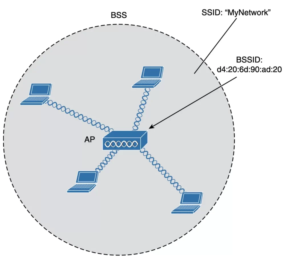
The area where the AP’s signal is usable establishes the boundary of the BSS. This area is known as the basic service area (BSA) or cell. Cells can be circular (Figure 26-4) or have other shapes, depending on the antenna that is connected to the AP and on the physical surroundings that might affect the AP’s signals.
The AP’s role at the center of the BSS is to manage the BSS. “The AP serves as a single point of contact for every device that wants to use the BSS” (p. 669). The AP advertises the existence of the BSS making it possible for devices to find the BSS and try to join.
>The AP uses a unique BSS identifier (BSSID) that is based on the AP’s own radio MAC address to send wireless frames at Layer 2 over the air. Wireless devices have unique MAC addresses to send wireless frames at Layer 2 over the air, just like wired Ethernet devices each have a unique MAC address to send frames from a source to a destination over a Layer 2 network. The BSSID can be thought of as a machine-readable name tag that uniquely identifies the BSS ambassador (the AP).
>The AP advertises the wireless network with a Service Set Identifier (SSID), a text string containing a logical name. The SSID can be thought of as a nonunique, human-readable name tag that identifies the wireless service. A SSID is a name that identifies a BSS.
Each BSS has a unique SSID. When a wireless device connects to a BSS, it sends a broadcast message with the SSID of the BSS that it wants to connect to. The AP then responds to the message and allows the device to connect to the BSS. Membership with the BSS is called an association.
The AP and its associated clients make up a standalone network.
A wireless device must send an association request to the AP and the AP must either grant or deny the request. Once associated, a device becomes a client, or an 802.11 station (STA), of the BSS.
Most communications to and from a wireless client associated with a BSS must pass through the AP. Data frames can be relayed to or from the AP by using the BSSID as a source or destination address. By sending data through the AP first, the BSS remains stable and under control.
Note, wireless frames are freely available over the air to anyone within range listening on the same channel (and hence they should be encrypted). “Only the BSSID value contained within the frames indicates that the intended sender or recipient is the AP” (Odom, 2020, p. 670).
Distribution System (DS)
A BSS involves a single AP and no explicit connection into a regular Ethernet network. If wireless clients need to communicate with other devices that are not members of the BSS, an AP can uplink into an Ethernet network because it has both wireless and wired capabilities. The 802.11 standard refers to the upstream wired Ethernet as the distribution system (DS) for the wireless BSS. In Figure 26-6, the AP maps VLAN 10 to the wireless LAN using SSID “MyNetwork.” Clients associated with the “MyNetwork” SSID will appear to be connected to VLAN 10.
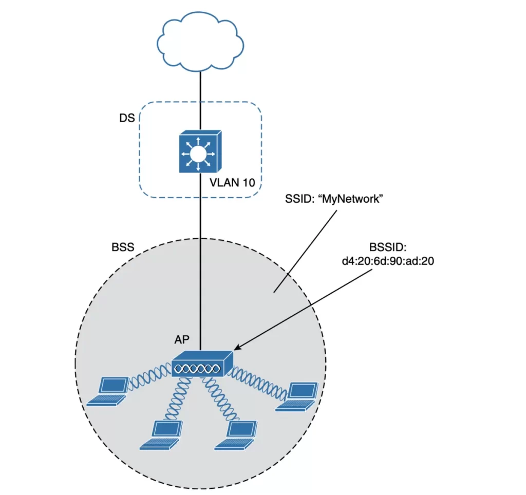
You can think of an AP as a translational bridge, where frames from two dissimilar media (wireless and wired) are translated and then bridged at Layer 2. In simple terms, the AP is in charge of mapping a virtual local-area network (VLAN) to an SSID. (Odom, 2020, p. 670)
Multiple VLANs can be mapped to multiple SSIDs, whereby the AP is connected to a switch by a trunk link that carries the VLANs.
In Figure 26-7, VLANs 10, 20, and 30 are trunked to the AP over the DS. The AP uses the 802.1Q tag to map the VLANs to the SSIDs. For example, VLAN 10 is mapped to SSID “MyNetwork,” VLAN 20 is mapped to SSID “YourNetwork,” and VLAN 30 to SSID “Guest.”
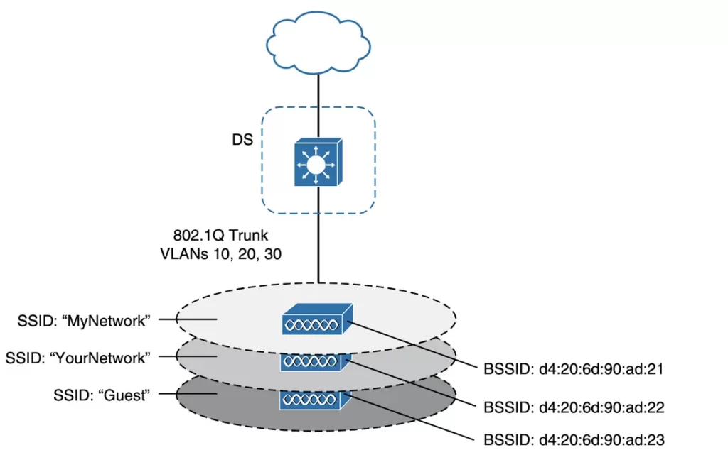
In effect, when an AP uses multiple SSIDs, it is trunking VLANs over the air, and over the same channel, to wireless clients. The clients must use the appropriate SSID that has been mapped to the respective VLAN when the AP was configured. The AP then appears as multiple logical APs—one per BSS—with a unique BSSID for each. With Cisco APs, this is usually accomplished by incrementing the last digit of the radio’s MAC address for each SSID. (p. 671)
Even though an AP can broadcast and support multiple logical wireless networks, each SSID covers the same geographic area. This is because the AP uses the same transmitter, receiver, antennas, and channel for every SSID that it supports. However, it is important to note that multiple SSIDs can give an illusion of scale. This is because wireless clients can be distributed across many SSIDs, but all of those clients must share the same AP’s hardware and must contend for airtime on the same channel.
In other words, having multiple SSIDs does not necessarily mean that you will have more bandwidth or better performance. In fact, it can actually have the opposite effect if too many clients are connected to the same AP.
A few things to keep in mind when using multiple SSIDs:
- Make sure that you use different SSIDs for different purposes. For example, you could use one SSID for guests and another SSID for employees. This will help to keep your network secure and prevent unauthorized access.
- Use different security settings for each SSID. This will help to protect your data from unauthorized access.
- Monitor your network traffic to make sure that you are not overusing your AP’s bandwidth. If you are overusing your bandwidth, you may need to upgrade your AP or move it to a different location.
By following these tips, you can use multiple SSIDs without compromising the security or performance of your wireless network.
Extended Service Set (ESS)
We learned about how a single AP can provide a BSS for a cell area. Now we look at how multiple APs can be connected to form an extended service set (ESS) for a larger network.
To extend the coverage area of a wireless network, you can add more APs and spread them out geographically. This will create overlapping coverage areas, which will allow devices to connect to the AP that provides the strongest signal.
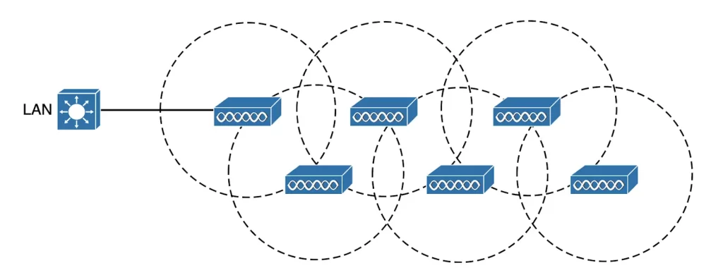
When APs are placed at different geographic locations and interconnected by a switched infrastructure, we get what the 802.11 standard calls an extended service set (ESS), as shown in Figure 26-8.
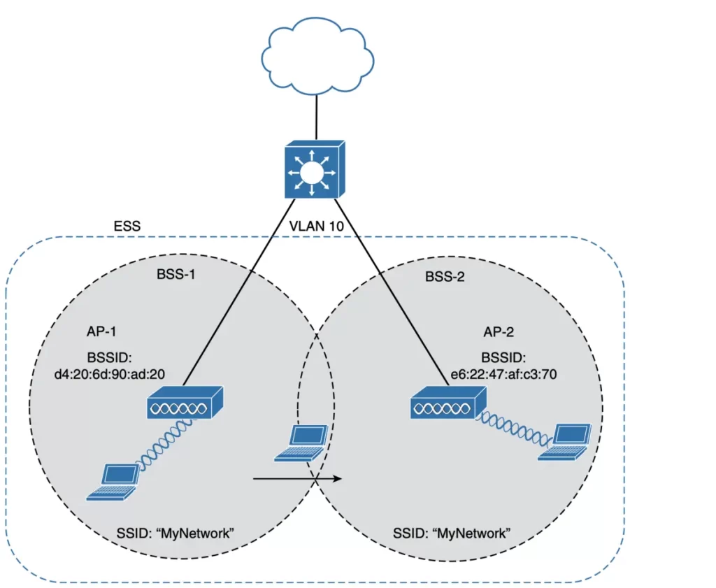
The goal is to make multiple APs cooperate so that from a client’s perspective the wireless service is consistent and seamless. It is best practice to define the same SSIDs on all APs in an ESS. This is because it would be very inconvenient for users to have to reconfigure their devices every time they move from one AP’s coverage area (cell) to another. When you define the same SSIDs on all APs in an ESS, users can simply roam between APs without having to do anything. This is because their devices will automatically connect to the AP that provides the strongest signal.
Notice that each cell in Figure 26-8 has a unique BSSID, but both cells share a common SSID. The SSID will remain the same regardless of a client’s location within the ESS and the client can always distinguish one AP from another.
In an ESS, a wireless client can associate with one AP while it is physically located near that AP. If the client later moves to a different location, it can automatically associate with a different nearby AP. This process of moving from one AP to another is called roaming.
Each AP in an ESS offers its own BSS on its own channel. This is done to prevent interference between the APs. When a client device roams from one AP to another, it must scan the available channels to find a new AP (and BSS) to roam toward. In effect, the client is roaming from BSS to BSS, and from channel to channel.
Independent Basic Service Set (IBSS)
The 802.11 standard allows two or more wireless devices to communicate directly with each other without the need for an AP. This is known as an ad hoc wireless network or an independent basic service set.
To create an IBSS, one of the devices must take the lead and start advertising a network name and the necessary radio parameters, similar to how an AP would. Other devices can then join the network as needed. IBSSs are intended to be organized in an impromptu and distributed manner; as a result, they do not scale well beyond eight to ten devices.
Other wireless topologies
Wireless APs can be configured to operate in noninfrastructure modes when a normal BSS cannot provide the needed functionality. The most common modes are repeater, workgroup bridge, outdoor bridge, and mesh network.
Repeater
To extend wireless coverage beyond a single cell’s coverage range (footprint), additional APs and their wired connections can be added to an existing BSS. And normally, this would be done via a wired connection to the switch, as we saw in Figure 26-8. But if the cable distance is too big to support Ethernet communication between a new AP and a switched infrastructure or DS, an AP configured for repeater mode can be used.
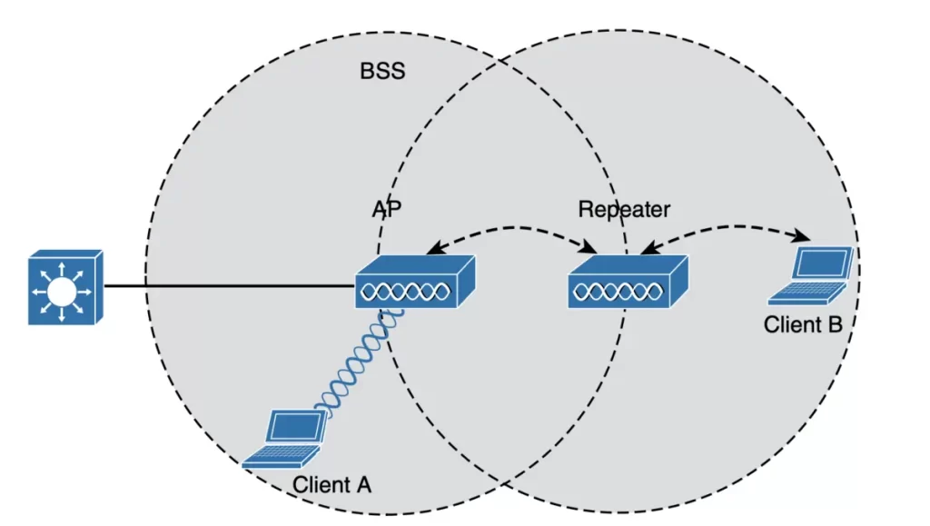
A wireless repeater takes the signal it receives and repeats or retransmits it in a new cell area around the repeater. To maintain an effective throughput, a repeater preferably uses two transmitters and two receivers to keep the original and repeated signals isolated on different channels. One transmitter and receiver pair is dedicated to signals in the repeater’s own cell and the other pair is dedicated to signals in the AP’s cell.
Workgroup Bridge (WGB)
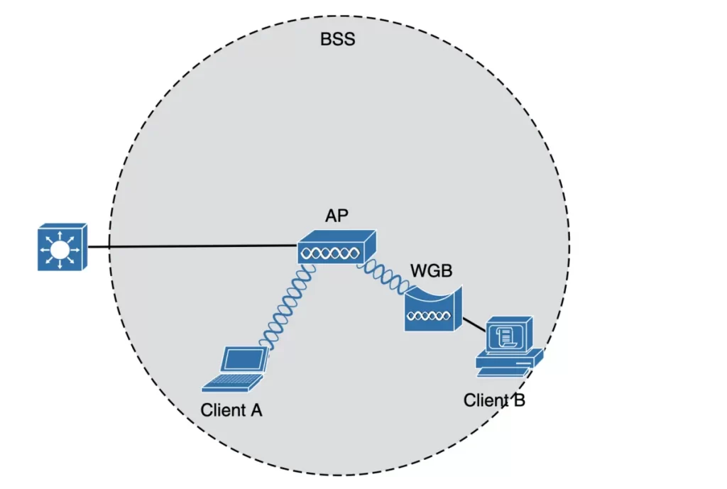
For a device not designed for wireless connection, a workgroup bridge (WGB) is used to connect a device’s wired network adapter to a wireless network. This is useful for connecting devices without a wireless adaptor to an AP. WGB acts as a wireless client of a BSS, as an external wireless network adapter for a device that has none.
Figure 26-11 shows an AP providing a BSS. Client A is a regular wireless client, while Client B is associated with the AP through a WGB.
Types of workgroup bridges :
■ Universal workgroup bridge (uWGB): A single wired device can be bridged to a wireless network.
■ Workgroup bridge (WGB): A Cisco-proprietary implementation that allows multiple wired devices to be bridged to a wireless network.
Outdoor Bridge
● Outdoor bridge – point-to-point or point-to-multipoint wireless bridge between distant wired networks.
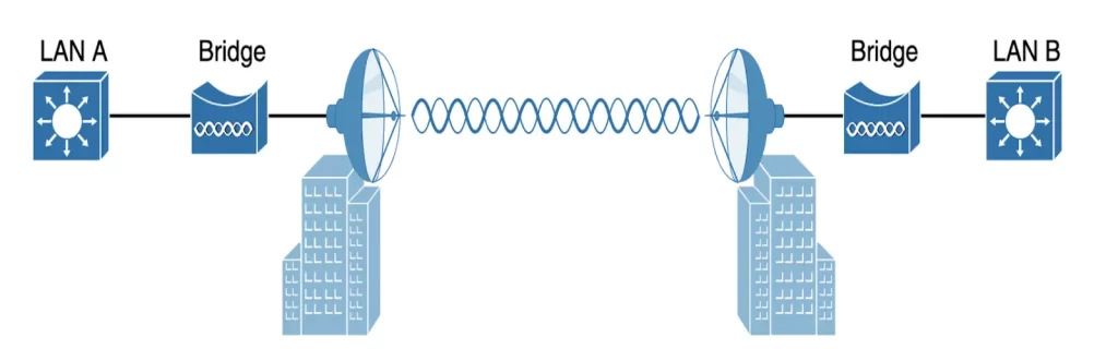
An AP can be configured to act as a bridge to form a single wireless link between buildings or between cities from one LAN to another. A point-to-point bridged link can be used If the LANs at two locations need to be bridged.
One AP configured in bridge mode is needed on each end of the wireless link. Special purpose antennas are normally used with the bridges to focus their signals in one direction—toward the antenna of the AP at the far end of the link. This maximizes the link distance, as shown in Figure 26-12. (p. 676)
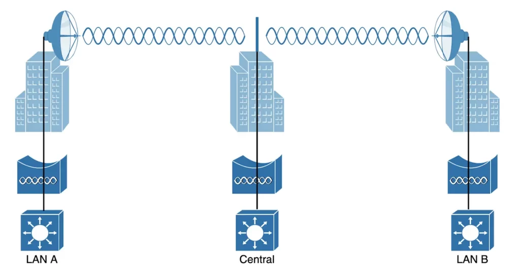
Alternatively, when LANs at multiple sites need to be bridged together, a point-to-multipoint bridged link allows a central site to be bridged to several other sites.
The central site bridge is connected to an omnidirectional antenna, such that its signal is transmitted equally in all directions so that it can reach the other sites simultaneously. The bridges at each of the other sites can be connected to a directional antenna aimed at the central site. Figure 26-13 shows the point-to-multipoint scenario. (p. 676)
Mesh Network
● Mesh network – multiple access points bridged in a daisy-chain.
In a mesh topology, wireless traffic is bridged from one AP to another in a sequential manner, as a daisy-chain, using a different wireless channel. Mesh APs can use two radios, one in each frequency channel. Each AP typically creates a BSS on one channel which wireless clients can associate with. Client traffic is then typically forwarded from one AP to another over other channels as a backhaul network. At the edge of the mesh network, the backhaul traffic is forwarded to the wired LAN infrastructure.
A typical mesh network is illustrated in Figure 26-14. With Cisco APs, you can build a mesh network indoors or outdoors. The mesh network runs its own dynamic routing protocol to work out the best path for backhaul traffic to take across the mesh APs.
RF (radio frequency) overview
How can an electrical signal be sent across free space?
Radio signals are generated by a transmitter which sends an alternating current into an antenna which radiates electromagnetic waves (created by the alternating current).
The signal must keep alternating by cycling up and down, to keep the electromagnetic wave pushing ever outward.
Electromagnetic waves do not travel in a straight line. Instead, they travel by expanding in all directions away from the antenna.
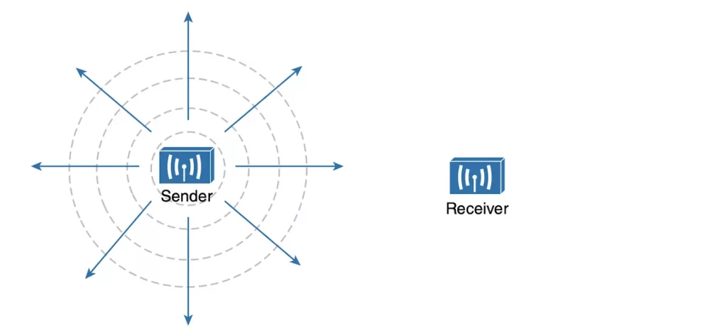
When electromagnetic waves reach a receiver’s antenna, they cause an electric current to flow through the antenna. If all goes well, the received signal will be a close replica of the original transmitted signal.
Electromagnetic waves can be measured and described in several ways. One fundamental property is the frequency of the wave, the number of times the signal makes one complete up and down cycle in 1 second. Figure 26-19 shows how a cycle of a wave can be described.
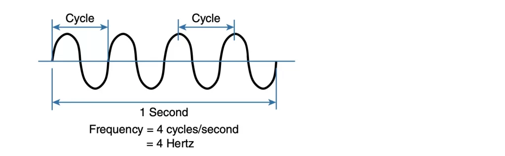
A hertz (Hz) is the most commonly used frequency unit and is one cycle per second.
Table 26-2 Frequency Unit Names (Odom, 2020, p. 679)
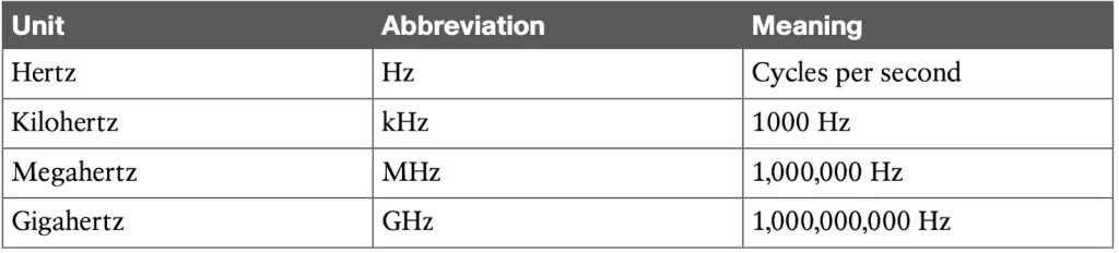
Figure 26-20 shows a simple representation of the continuous frequency spectrum ranging from 0 Hz to 1022 Hz. At the low end of the spectrum are frequencies too low to be heard by the human ear, followed by audible sounds. The highest range of frequencies contains light, followed by X, gamma, and cosmic rays.
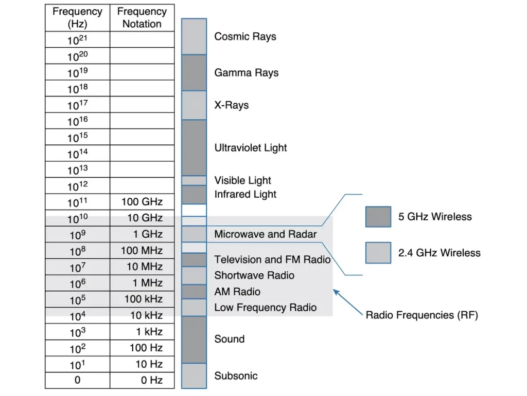
The RF range (~3 kHz to 300 GHz) includes many types of radio communication, including:
>Low-frequency radio: This type of radio communication is used for applications such as navigation and timekeeping.
>AM radio: This type of radio communication is used for broadcasting music and news.
>Shortwave radio: This type of radio communication is used for long-distance communication.
>Television: This type of radio communication is used for broadcasting video and audio.
>FM radio: This type of radio communication is used for broadcasting music and talk shows.
>Microwave: This type of radio communication is used for applications such as cooking and telecommunications.
>Radar: This type of radio communication is used for detecting objects and measuring their distance, speed, and direction.
The microwave category contains the two main frequency ranges that are used for wireless LAN communication: 2.4 and 5 GHz.
Wireless bands and channels
A range of frequencies is often referred to as a band of frequencies. For example, AM radio stations use the frequency range from 530 kHz to around 1710 kHz, which is why it is also known as the AM band or the AM broadcast band.
The 2.4-GHz band refers to the frequency range 2.400 to 2.4835 GHz.
The 5-GHz band contains the following four separate and distinct bands:
5.150 to 5.250 GHz
5.250 to 5.350 GHz
5.470 to 5.725 GHz
5.725 to 5.825 GHz
You do not need to memorize the band names or exact frequency ranges, but be aware of the two main bands at 2.4 and 5 GHz.
Here are some additional details about the bands used for Wi-Fi connections:
- The 2.4 GHz band is the older of the two bands and has a longer range, but it can also be more crowded with interference from other devices, such as microwaves and baby monitors.
- The 5 GHz band is newer and has a shorter range, but it can offer faster speeds and less interference.
Bands are usually divided into a number of distinct channels. Each channel is known by a channel number and is assigned to a specific frequency. Channels are defined by a national or international standards body so that they can be used consistently in all locations. Figures 26-21 and 26-22 (p. 681) show the channel layout for the 2.4 and 5 GHz bands, respectively.
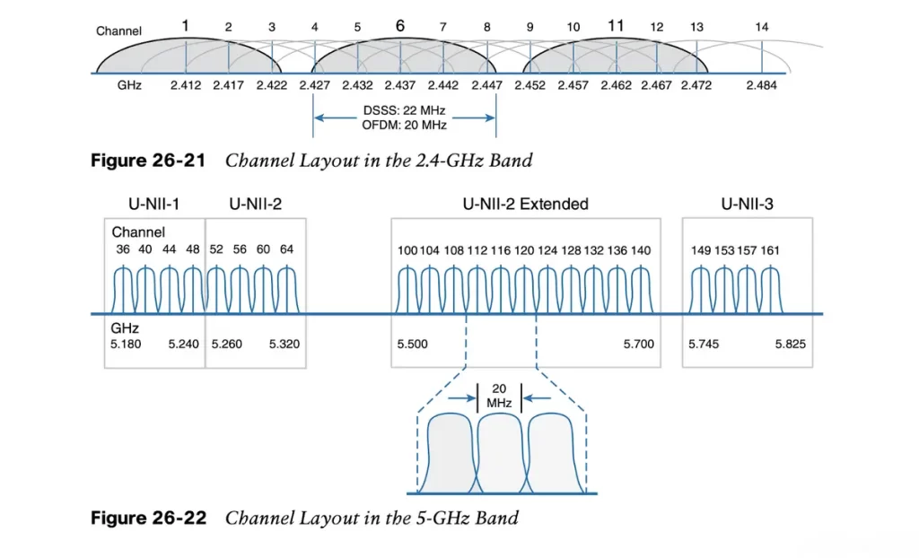
In the 5-GHz band, an AP can use any channel number without affecting any APs that use other channel numbers, because each channel is allocated a frequency range that does not encroach on or overlap the frequencies allocated for any other channel. In other words, the 5-GHz band consists of nonoverlapping channels.
Each of the channels in the 2.4-GHz band is much too wide to avoid overlapping the next lower or upper channel number. Each channel covers the frequency range that is allocated to more than four consecutive channels.
The only way to avoid any overlap between adjacent channels is to configure APs to use only channels 1, 6, and 11. Even though there are 14 channels available to use, you should always strive for nonoverlapping channels in your network. (p. 682)
In open space, RF signals reach further on the 2.4-GHz band than on the 5-GHz band and they tend to penetrate walls and objects easier at 2.4 GHz than 5 GHz. Because the 2.4-GHz band has only three nonoverlapping channels available the chances of signal interference with neighboring APs using the same channels is greater. The 5-GHz band has many more channels available to use, hence is less crowded and experiences less interference.
APs and wireless standards
Wireless devices and APs must be compatible with each other in order to communicate. This means that they must be able to operate on the same frequency band and they must support the same parts of the 802.11 standard. For example, a 5-GHz wireless phone can only communicate with an AP that offers Wi-Fi service on 5-GHz channels. A 2.4-GHz wireless phone cannot communicate with a 5-GHz AP. In addition to the frequency band, wireless devices and APs must also support the same parts of the 802.11 standard.
The 802.11 standard is a set of specifications for wireless networking. It has been updated several times over the years, and each new version adds new features and capabilities.
The IEEE 802.11 standard has been amended several times to add new features and improve performance. These amendments define important characteristics of Wi-Fi networks, such as data rates, methods used to transmit and receive data, and so on.
You should be aware of several amendments that define important characteristics such as data rates, methods used to transmit and receive data, and so on.
For the CCNA 200-301 exam, you need to be aware of which band each of the amendments listed in Table 26-3 uses. The ENCOR 350-401 exam goes into more detail about the data rates, modulation and coding schemes used by each amendment.
Table 26-3 Basic Characteristics of Some IEEE 802.11 Amendments (Odom, 2020, p. 682)
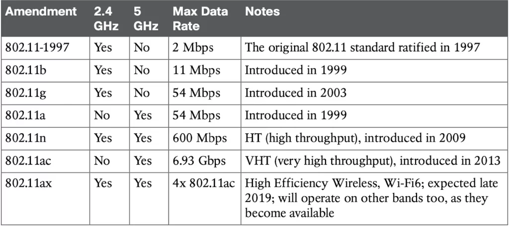
Wireless client devices and APs can be compatible with more than one amendment. However, a client and an AP can communicate only if they both support the same amendment. Supported amendments for a wireless device are listed in the device specifications in a single string, separated by slashes. For example, a device that supports 802.11b/g/a/n/ac will support 802.11b, 802.11g, 802.11a, 802.11n, and 802.11ac.
You should become familiar with Table 26-3 so that you can know which bands a device can use based on its 802.11 amendment support. While wireless clients typically associate with an AP on one band at a time, APs can usually operate on two bands simultaneously to support clients present on each band.
The operating system, wireless adapter driver, and other internal settings will determine which band is used to connect to an AP. The client will typically try to connect to the band that offers the best signal quality. However, the client can also be configured to connect to a specific band.
A wireless client can initiate an association with an AP on one band and then automatically switch to the other band if the signal quality is better there. This is called band steering. Band steering can help to improve the performance of a wireless network by ensuring that clients are always connected to the band that offers the best signal quality.
NOTE – Cisco APs have dual radios (sets of transmitters and receivers) to support BSSs on one 2.4-GHz channel and other BSSs on one 5-GHz channel simultaneously. Some models also have two 5-GHz radios that can be configured to operate BSSs on two different channels at the same time, providing wireless coverage to higher densities of users that are located in the same vicinity. (Odom, 2020, p. 683)
Practice quiz questions
You can find four quiz questions and answers for this lesson in Odom, 2020, pp. 664-668.
Key references
Odom, W. (2020). Chapter 26. Fundamentals of Wireless Networks, CCNA 200-301 Official Cert Guide (pp. 664-684), Volume 1. Cisco Press.
Related content
Cisco wireless architectures and AP modes
Compliance frameworks and industry standards
Configure WLAN within the GUI using WPA2 PSK
How data flow through the Internet
How to break into information security
IT career paths – everything you need to know
Job roles in IT and cybersecurity
The GRC approach to managing cybersecurity
The Security Operations Center (SOC) career path
Back to DTI Courses


