This lesson covers two Layer 2 discovery protocols, CDP (Cisco Discovery Protocol) and LLDP (Link Layer Discovery Protocol). CDP and LLDP configuration and verification are covered in topic 2.3 of the CCNA exam blueprint, which says you must be able to configure and verify Layer 2 discovery protocols CDP and LLDP. First, Layer 2 discovery protocols are introduced. Then the discussion focuses on CDP verification and configuration. Finally, LLDP configuration and verification are discussed. This post constitutes Issue 30 of my CCNA 200-301 study notes.
- Layer 2 discovery protocols introduction
- CDP (Cisco Discovery Protocol) introduction
- CDP verification (show commands)
- CDP show commands summary
- CDP configuration
- LLDP (Link Layer Discovery Protocol) introduction
- LLDP configuration
- LLDP verification (show commands)
- LLDP show commands summary
- CDP Wireshark capture
- LLDP Wireshark capture
- Command review (CDP and LLDP)
- Key learnings
- Practice quiz questions
- Key references
You may also be interested in CCNA 200-301 study notes.
Layer 2 discovery protocols introduction
*Layer 2 discovery protocols are so called because they operate at Layer 2. Layer 2 discovery protocols such as CDP and LLDP share information with, and discover information about, neighboring connected devices.
*CDP and LLDP shared information includes host name, IP address, and device type. Although CDP and LLDP are Layer 2 discovery protocols, they can be used to share Layer 3 information such as IP addresses.
*CDP is a Cisco proprietary protocol. CDP was the original, and LLDP was later invented to have an industry standard version. LLDP is an industry standard protocol, IEEE 802.1AB.
*If you are using only Cisco devices in your network, using only CDP is fine. However if there is a mix of vendors, such as Cisco routers, Juniper switches, and Palo Alto firewalls, you will have to use LLDP.
*Because these protocols share information about the devices in the network, they can be a security risk. Whether to use them or not is a decision that will have to be made by the network engineer.
To demonstrate how these protocols work, here are two directly connected devices, R1 and SW1.
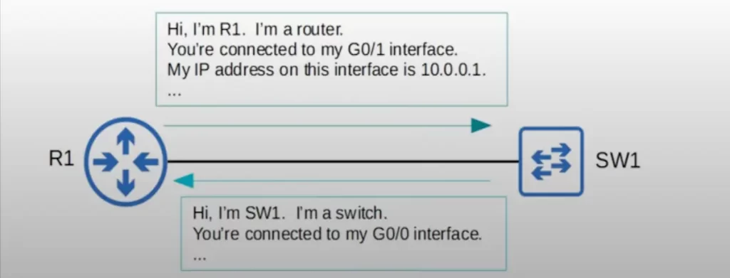
R1 will periodically send frames to SW1, telling it information like R1’s hostname, device type, interface ID, and interface IP address. SW1 likewise will periodically send frames to R1 telling R1 about SW1.
CDP (Cisco Discovery Protocol) introduction
*CDP is enabled by default on Cisco devices, such as Cisco routers, Cisco switches, Cisco firewalls, and Cisco IP phones.
*CDP messages are periodically sent to multicast MAC address 0100.0CCC.CCCC.
For the CCNA exam, you need to remember this MAC address, as well as the MAC addresses used by LLDP, STP, PVST, HSRP, and VRRP:
CCNA networking standards (MAC addresses, timers, etc.)
*CDP messages use a multicast MAC address but the messages are not forwarded to other devices. When a device receives a CDP message, it processes and then discards the message. It does not forward it to other devices. Only directly connected neighbors can become CDP neighbors.
*CDP messages are sent once every 60 seconds by default out of all interfaces which are in an up state. These are the messages that contain information such as host name and IP address. When a device receives the CDP messages from a neighboring device, it adds an entry for the device in its CDP neighbor table.
*If a neighbor is disconnected, there is a default CDP holdtime of 180 seconds. If a message is not received from a neighbor for 180 seconds, the neighbor is removed from the CDP neighbor table.
*There are two versions of CDP, version 1 and version 2. Version 2 is used by default. Version 2 provides some additional advanced features such as the ability to identify native VLAN mismatches. CDP version 1 is very old so you’ll probably never need to use it.
Let’s get right into the CLI to see exactly what information is shared by CDP.
CDP verification (show commands)
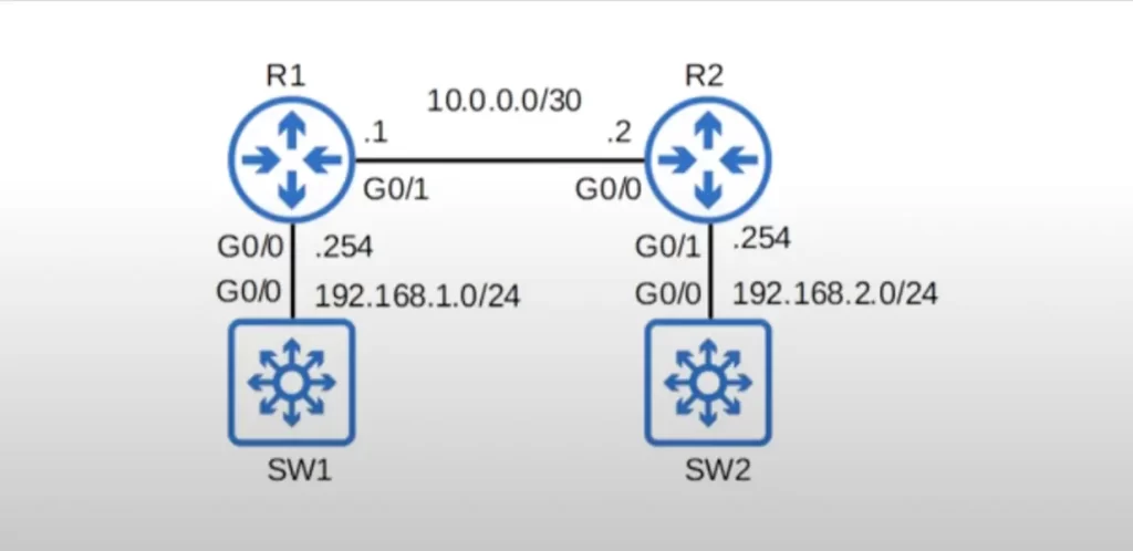
Here is our demo network. Two routers and two multilayer switches. We are not using any Layer 3 functions on the switches.
Let’s look at a few CDP show commands before looking at the CDP neighbor table. We will look at three CDP show commands, SHOW CDP, SHOW CDP TRAFFIC, and SHOW CDP INTERFACE.
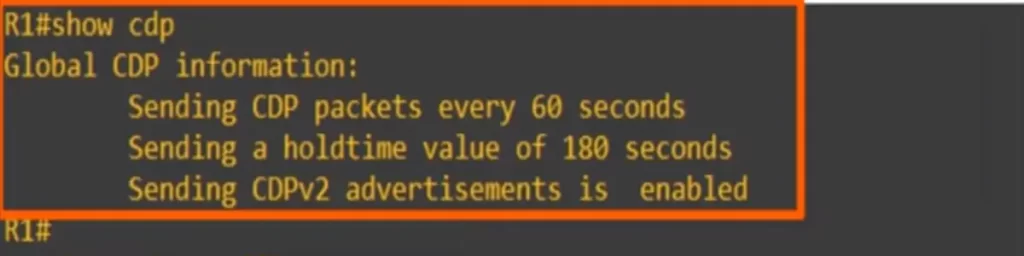
SHOW CDP tells us the CDP timer, 60 seconds by default, the CDP holdtime, 180 seconds by default, and which version of CDP is being used.
The SHOW CDP TRAFFIC command tells us how many CDP packets, how many CDP advertisements, the device has sent and received.
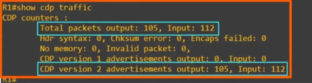
>In this case, R1 sent 105 CDP messages and received 112 CDP messages, and all of those messages were CDP version 2 messages.
If you enter SHOW CDP INTERFACE you will get some basic information about all interfaces. You can also specify a certain interface when entering the command.
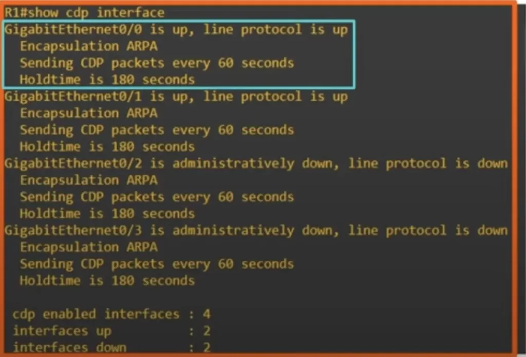
>In the blue rectangle in the above CLI output, you can see the information for G0/0. You can see the same CDP message timer and holdtime as above. Notice the entry “Encapsulation ARPA”. ARPA is a type of Ethernet encapsulation. This type of Ethernet is also known as Ethernet 2. Ethernet types are beyond the scope of the CCNA.
>Note at the bottom of the above CLI output how many CDP enabled interfaces are there, and how many interfaces are in an up state and a down state.
Now let’s look at R1’s CDP neighbor table.
Use the command SHOW CDP NEIGHBORS to view it.
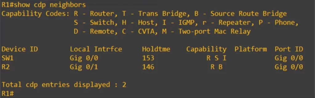
>Device ID column lists the host name of each of R1’s CDP neighbors. R1 has received CDP messages from SW1 and R2.
>Local interface column gives the interface on the local device, R1. SW1 is connected to R1’s G0/0 interface, and R2 is connected to R1’s G0/1 interface, as shown in the network diagram (our demo network).
>Holdtime column: holdtime will reset to 180 each time R1 receives a CDP message from the neighbor. With the default timers, the hold timer should count down to 120, by this time, normally, R1 would receive a CDP message and reset the timer to 180. This cycle repeats. If this timer reaches 0, the neighbor will be removed from the CDP neighbor table.
>Capability column helps you identify what kind of device you are connected to. SW1 has the letters R, S, and I. R is router. S is switch. I is IGMP. SW1 is listed as both R and S because SW1 is a multilayer switch, so it has routing capabilities. IGMP is related to multicast and is beyond the CCNA. R2 has two letters, R and B. B is source route bridge. Source route bridge is beyond the scope of the CCNA.
>Platform column displays the model of the neighboring device. Cisco has various models of routers, switches, firewalls, etc., and the model will be displayed here. But nothing is showing because the CLI is a virtual device running in GNS3, with its own limitations.
>Port ID column tells you the port ID on the neighboring device. So R1 is connected to SW1’s G0/0 interface and R2’s G0/0 interface.
We can use SHOW CDP NEIGHBORS DETAIL to view more information for each neighbor. Here’s SW1’s entry.
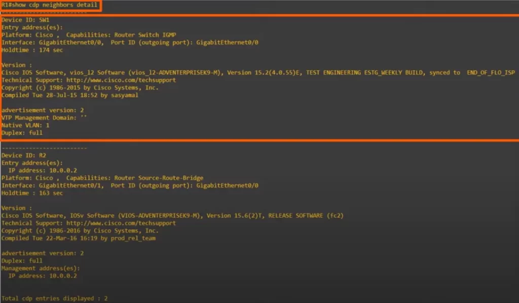
>The SHOW CDP NEIGHBORS DETAIL command lets you see the IOS version running on the neighbor device. This information does not show up with the regular SHOW CDP NEIGHBORS command.
>Because SW1 is a switch, you can also see VTP information here. VTP is a Cisco proprietary protocol.
>You can also see the native VLAN of SW1’s interface, currently it’s the default of 1.
>The duplex setting of SW1’s interface is also displayed.
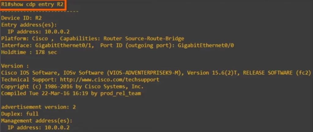
There is another command which lets you view this detailed information for a single neighbor, SHOW CDP ENTRY, followed by the neighbor’s host name, R2 in this case. The output here is exactly the same as in SHOW CDP NEIGHBORS DETAIL, but it only shows the specified neighbor.
CDP show commands summary
R#show cdp
→to display basic information about CDP (timer, holdtime, CDP version)
R#show cdp traffic
→to display the number of messages sent and received
R#show cdp interface
→to display the interfaces CDP is enabled on
R#show cdp neighbors
→to display information about CDP neighbors
R#show cdp neighbors detail
→to list CDP neighbors with more detailed information
R#show cdp entry host-name
→to display the same information as above for a specified neighbor
CDP configuration
If you want to use CDP in your network you typically do not have to do any configurations, since Cisco devices have CDP activated by default.
Here are the CDP configuration commands you should know for the CCNA: CDP RUN, CDP ENABLE, CDP TIMER, CDP HOLDTIME, and CDP ADVERTISE-V2.
*CDP is globally enabled on Cisco devices by default. Each interface also has CDP enabled by default.
*To enable or disable CDP globally, use the CDP RUN command from global config mode. Use CDP RUN to enable it, and NO CDP RUN to disable it.
R(config)#[no] cdp run
*You can enable or disable CDP on a per-interface basis. To enable CDP on an interface, from interface config mode, use CDP ENABLE. Use NO in front of the command to disable it.
R(config-if)#[no] cdp enable
*You can configure the CDP timer, how often CDP messages are sent, with the CDP TIMER command from global config mode.
R(config)#cdp timer seconds
*You can configure the holdtime with cdp holdtime.
R(config)#cdp holdtime seconds
*You can enable CDP version 2, which is the default state, with cdp advertise-v2, or use no in front of the command to disable it and use version 1.
R(config)#[no] cdp advertise-v2
LLDP (Link Layer Discovery Protocol) introduction
*LLDP is a vendor-neutral protocol that is defined in the IEEE 802.1AB standard. This means that all network devices that support LLDP will be able to communicate with each other, regardless of the manufacturer of the device.
Here is a quote from the IEEE 802.1AB standard that describes LLDP:
“LLDP is a link layer protocol that provides a means for devices on a network to exchange information about their capabilities, management addresses, and other pertinent information. This information can be used by network management applications to build a topology map of the network, as well as to troubleshoot problems.”
LLDP is a valuable tool for network administrators because it can help them to:
- Build a topology map of the network: LLDP can be used to collect information about the devices that are connected to a network, as well as the links between those devices. This information can be used to create a map of the network, which can be helpful for troubleshooting problems and planning network changes.
- Troubleshoot network problems: LLDP can be used to identify devices that are not responding or that are not connected to the network properly. This information can be helpful for troubleshooting network problems and restoring service.
*LLDP is usually disabled on Cisco devices by default, so it must be manually enabled.
*A device can run CDP and LLDP at the same time, although usually only one of them is used.
*LLDP messages are periodically sent to multicast MAC address 0180.C200.000E.
*Like in CDP, only directly connected devices can become LLDP neighbors. When a device receives an LLDP message, it processes and discards the message. It does not forward it to other devices.
*By default, LLDP messages are sent once every 30 seconds, half the time of CDP’s default 60 seconds.
*LLDP’s default holdtime is 120 seconds.
*LLDP also has an additional timer called the reinitialization delay, set at 2 seconds by default. If LLDP is enabled, either globally or on a specific interface, this timer will delay the actual initialization of LLDP. This timer may help in cases of flapping, when LLDP is rapidly enabled or disabled for some reason.
LLDP configuration
Let’s look at the LLDP configuration commands first, and then look at the SHOW commands.
LLDP is globally disabled by default, and it’s also disabled on each interface by default. To enable LLDP you need to enable it globally and then enable it on each interface.
LLDP configuration commands are similar to the CDP commands, the biggest difference is the interface configuration.
*To enable LLDP globally use LLDP RUN. This is the same as CDP, just replace the word CDP with LLDP.
R(config)#lldp run
If you want to disable it, use NO in front of the command.
Now let’s see the interface configurations.
CDP had only one command to enable the interface to send and receive CDP messages, CDP ENABLE. But in LLDP, you need to use two separate commands.
*To enable LLDP transmissions (tx) on an interface, use LLDP TRANSMIT on the interface. This causes the interface to start sending LLDP messages.
R(config-if)#lldp transmit
*To enable LLDP in the receive direction (rx) on an interface, use the LLDP RECEIVE command on the interface.
R(config-if)#lldp receive
Now let’s see how to configure each LLDP timer.
*The timer used to send messages is configured with LLDP TIMER, then the timer in seconds.
R(config)#lldp timer seconds
*The LLDP holdtime is configured with LLDP HOLDTIME, then the holdtime in seconds.
R(config)#lldp holdtime seconds
*The LLDP reinitialization timer is configured with LLDP REINIT, then the timer in seconds.
R(config)#lldp reinit seconds
LLDP verification (show commands)
LLDP has been enabled on all of these devices with the command LLDP RUN from global config mode, and LLDP TRANSMIT and LLDP RECEIVE on all interfaces. They are now running both CDP and LLDP.
Let’s check out some LLDP show commands, the LLDP equivalents of the ones we used for CDP. Those commands are very similar to their CDP equivalents.
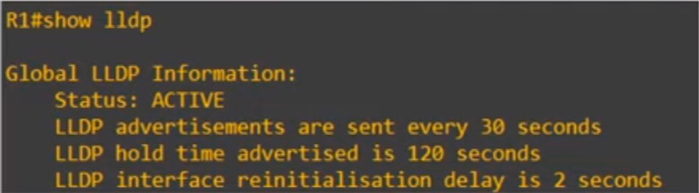
>First, SHOW LLDP gives the same information as SHOW CDP does for CDP. It shows that LLDP is enabled, and displays each of the LLDP timers, currently at the default settings of 30, 120, and 2 seconds.
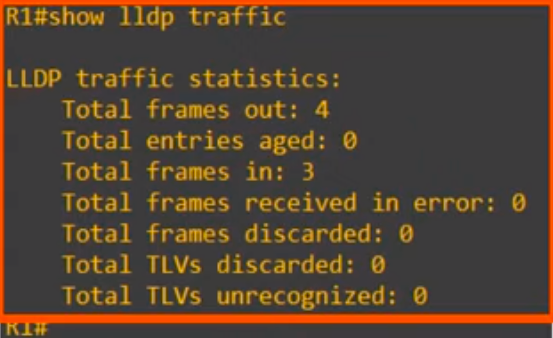
>SHOW LLDP TRAFFIC, similar to SHOW CDP TRAFFIC, shows statistics about how many LLDP frames were sent and received. In this case, 4 frames have been sent and 3 have been received by R1.
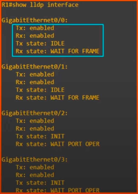
>Then we used SHOW LLDP INTERFACE. This shows whether TRANSMIT and RECEIVE are enabled or disabled on each interface, as well as the current Tx and Rx state. For example, for G0/0 both Tx and Rx are enabled. The Tx state is IDLE, waiting before it sends the next LLDP frame to SW1. And the Rx state is WAIT FOR FRAME, waiting to receive the next LLDP frame from SW1.
Now let’s check R1’s LLDP neighbor table.
The command is SHOW LLDP NEIGHBORS.
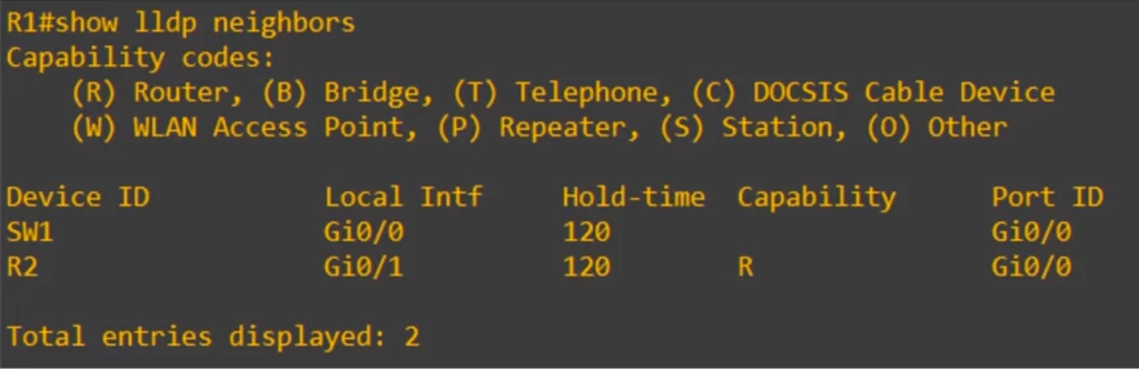
>First up, the device ID, the host name, of each neighbor is displayed.
>Then the local interface. Just like in SHOW CDP NEIGHBORS, this is the interface of the local device, R1 in this case.
>Then the hold time. This is a little different than in SHOW CDP NEIGHBORS. In SHOW CDP NEIGHBORS, you could watch the timer count down from 180, and then reset to 180 when a CDP message is received. However SHOW LLDP NEIGHBORS just displays the holdtime that is configured on this device, 120 seconds.
>Then the capability column. Notice, there is no entry for SW1. You would normally expect to see B for Bridge as an entry for SW1 (there is no SWITCH capability code). But B is not displaying for SW1. This is likely because these virtual devices are being run in GNS3 so it is not detecting that SW1 is an active switch, but when we look at SHOW LLDP NEIGHBORS DETAIL, in the below diagram, we will see this bridge code for SW1.
>Just like in SHOW CDP NEIGHBORS, the last column is the port ID, the interface ID of the neighboring device. R1 is connected to SW1’s G0/0 interface and R2’s G0/0 interface.
Here’s SHOW LLDP NEIGHBORS DETAIL on R1. The output is too long. For convenience, R2’s entry is cut off a little at the bottom.
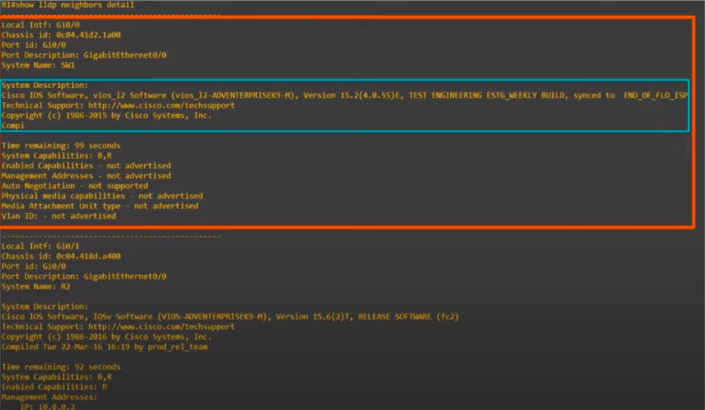
>Notice SW1’s entry gives us additional information, such as the operating system version running on SW1.
>We can also see the ‘time remaining’ in the countdown to the default holdtime of 120 seconds.
>Notice, LLDP has two fields for the device’s capabilities, shown when you use SHOW LLDP NEIGHBORS DETAIL: System capabilities and enabled capabilities.
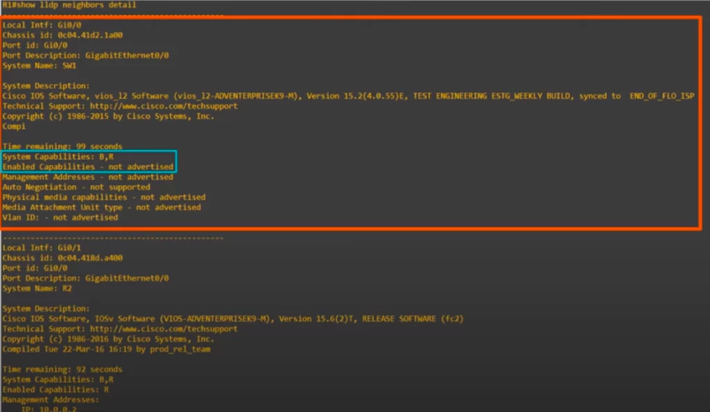
If you look at system capabilities, you can see B and R. B is for bridge, meaning switch. And R is for Router. This is what you would expect because SW1 is a multilayer switch. It has the functions of both a router and a switch. However, in this case the “enabled capabilities” field displays “not advertised”.
If we use the IP ROUTING command on SW1, SW1’s router functionality will be enabled and the “R” from “system capabilities” will show in “enabled capabilities”. However, the reason B is not displayed next to enabled capabilities is likely because SW1 is a virtual device running in GNS3 and it’s not recognized as an active switch.
*Like in CDP, there is a command you can use to view the exact same output as SHOW LLDP NEIGHBORS DETAIL but for a single neighbor instead of all neighbors. Use SHOW LLDP ENTRY, followed by the neighbor’s host name.
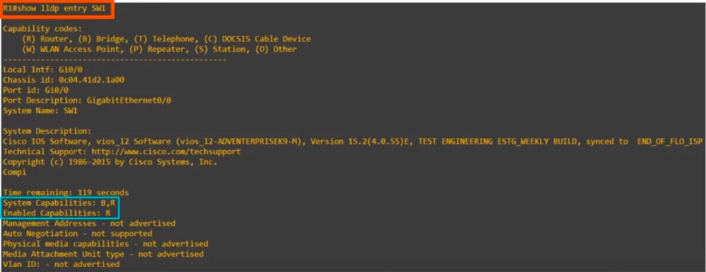
Before using this command IP ROUTING was enabled on SW1, and now you can see R is displayed next to enabled capabilities for SW1.
LLDP show commands summary
The LLDP show commands are the same as the CDP show commands, just replace the word CDP with LLDP.
R#show lldp
→to display basic information about LLDP (timers, version)
R#show lldp traffic
→to display how many LLDP messages were sent and received
R#show lldp interface
→to display which interfaces have tx/rx enabled
R#show lldp neighbors
→to display basic information about LLDP neighbors
R#show lldp neighbors detail
→to list LLDP neighbors with more detailed information
R#show lldp entry host-name
→to display the same information as above for a specified neighbor
CDP Wireshark capture
Let’s have a quick look at a couple of Wireshark captures, one for CDP and one for LLDP.
This is a CDP message sent from R1 to SW1.
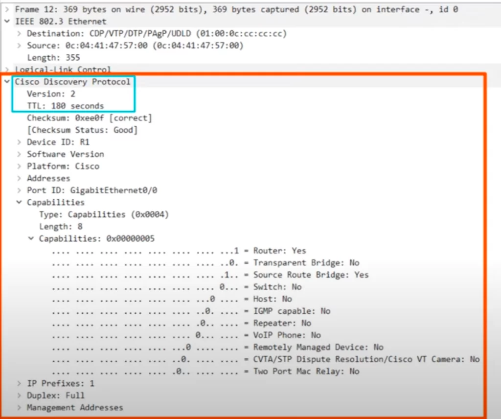
>Notice the CDP destination MAC address, 0100.0CCC.CCCC. But notice that Wireshark describes this destination MAC as CDP/VTP/DTP/PagP/UDLD. That’s because this same multicast MAC address is actually used for multiple protocols, not just CDP.
>Now, here’s the actual CDP information (enclosed in the orange rectangle). You can see that CDP version 2 is being used. The TTL, time to live, is the CDP holdtime.
>There are some other fields such as the device ID, this is being sent from R1, the version, platform, addresses, and port ID.
>We expanded the capabilities field, and you can see there is a ‘1’ for ‘Router’ and ‘Source Route Bridge’, those are the capabilities of R1.
Finally, notice that there is no IP packet inside of this Ethernet frame. These Layer 2 discovery protocols don’t use IP addresses, only MAC addresses.
LLDP Wireshark capture
And here’s an LLDP frame capture, this time a message that SW1 sent to R1.
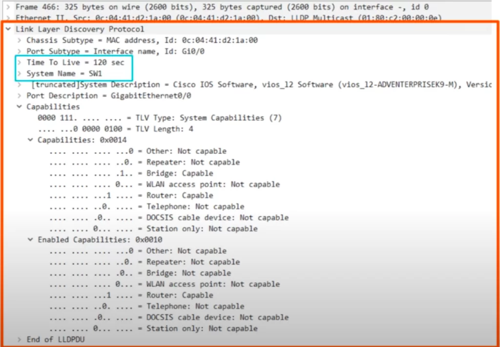
>First, notice the destination MAC address we saw earlier, 0180.C200.000E.
>And here’s the actual LLDP information (enclosed in the orange rectangle). The time to live, TTL, is the LLDP holdtime of 120 seconds, and you can see the system name, the host name, of the device which sent this message, SW1.
>Note the LLDP capabilities field. Just like we saw before, SW1’s capabilities are Bridge and Router, but its only enabled capability is router.
Command review (CDP and LLDP)
1. CDP (Cisco Discovery Protocol)
1.1. CDP verification (show commands)
R#show cdp
→to display basic information about CDP (timer, holdtime, CDP version)
R#show cdp traffic
→to display the number of CDP messages (advertisements) the device has sent and received
R#show cdp interface
→to display basic information about the interfaces CDP is enabled on. You can also specify a certain interface when entering the command
R#show cdp neighbors
→to display the CDP neighbor table
R#show cdp neighbors detail
→to view more information for each CDP neighbor – the IOS version running on the neighbor device, VTP information, and the native VLAN and duplex setting of the neighbor interface
R#show cdp entry host-name
→to display the same information as above for a specified neighbor
1.2. CDP configuration
R(config)#[no] cdp run
→to enable or disable CDP globally
CDP is globally enabled on Cisco devices by default. Each interface also has CDP enabled by default.
R(config-if)#[no] cdp enable
→to enable/disable CDP on a specific interface
R(config)#cdp timer seconds
→to configure the CDP timer
R(config)#cdp holdtime seconds
→to configure the CDP holdtime
R(config)#[no] cdp advertise-v2
→to enable/disable CDPv2
2. LLDP (Link Layer Discovery Protocol)
2.1. LLDP configuration
LLDP configuration commands are similar to the CDP commands, the biggest difference is the interface configuration.
LLDP is globally disabled by default, and it’s also disabled on each interface by default. To enable LLDP you need to enable it globally and then enable it on each interface.
R(config)#lldp run
→to enable LLDP globally. To disable it, use NO in front of the command
In LLDP, you need to use two separate commands to enable the interface to send and receive LLDP messages.
R(config-if)#lldp transmit
→to enable LLDP on specific interfaces in the transmit direction (tx)
R(config-if)#lldp receive
→to enable LLDP on specific interfaces in the receive direction (rx)
Now let’s see how to configure each LLDP timer.
R(config)#lldp timer seconds
→to configure the LLDP timer
R(config)#lldp holdtime seconds
→to configure the LLDP holdtime
R(config)#lldp reinit seconds
→to configure the LLDP reinitialization timer
2.2. LLDP verification (show commands)
The LLDP show commands are the same as the CDP show commands, just replace the word CDP with LLDP.
R#show lldp
→gives the same information as SHOW CDP does for CDP. It shows that LLDP is enabled, and displays each of the LLDP timers
R#show lldp traffic
→to display statistics about how many LLDP frames were sent and received
R#show lldp interface
→to show whether TRANSMIT and RECEIVE are enabled or disabled on each interface, as well as the current Tx and Rx state
R#show lldp neighbors
→to check the router’s LLDP neighbor table
R#show lldp neighbors detail
→to list LLDP neighbors with more detailed information
R#show lldp entry host-name
→to display the same information as above for a specified neighbor
Free CCNA | CDP & LLDP | Day 36 Lab – Notes
Key learnings
*Introduction to Layer 2 discovery protocols and their purpose.
*Introduction to CDP, Cisco’s Layer 2 discovery protocol.
*Introduction to LLDP, which was developed after CDP as an industry standard alternative.
Practice quiz questions
Quiz question 1
Which of the following commands show the configured CDP timers? Select two.
a) R1#show cdp
b) R1#show cdp traffic
c) R1#show cdp interface
d) R1#show cdp neighbors
The answers are a and c.
For four more practice questions for this lesson (plus a bonus one), visit Jeremy’s CDP & LLDP video lesson, cited below.
Key references
Note: The resources cited below (in the “Key references” section of this document) are the main source of knowledge for these study notes/this lesson, unless stated otherwise.
Free CCNA | CDP & LLDP | Day 36 | CCNA 200-301 Complete Course
Free CCNA | CDP & LLDP | Day 36 Lab | CCNA 200-301 Complete Course
Related content
Compliance frameworks and industry standards
How data flow through the Internet
How to break into information security
IT career paths – everything you need to know
Job roles in IT and cybersecurity
Network security risk mitigation best practices
The GRC approach to managing cybersecurity
The penetration testing process
The Security Operations Center (SOC) career path
Back to DTI Courses


