This post represents Part 3 of 3 of STP study notes for the CCNA. Because Rapid STP (RSTP) is superior to classic Spanning Tree, it is the default on most devices now. The CCNA exam topics list only mentions Rapid Spanning Tree: subsection 2.5 says you must be able to “Interpret basic operations of Rapid PVST+ Spanning Tree Protocol“.
This lesson focuses on Cisco’s version of RSTP, Rapid Per-VLAN Spanning Tree Plus (Rapid PVST+). This lesson builds on the foundations covered in Part 1 (STP root bridge election and root port selection) and Part 2 (Classic Spanning Tree port states) to discuss the basic operations of Rapid PVST+ STP. More specifically, this lesson focuses on RSTP port states (discarding, learning, and forwarding), RSTP port roles (alternate and backup), STP optional features built into RSTP (UplinkFast, BackboneFast, and PortFast), RSTP configuration in CLI, and RSTP link types (edge, point-to-point, and shared). This post constitutes Issue 17 of my CCNA 200-301 study notes.
- Comparison of STP versions (standard vs Cisco)
- Some similarities between STP and RSTP
- Some differences between STP and RSTP
- RSTP port states (discarding, learning, and forwarding)
- RSTP port roles (alternate and backup)
- RSTP alternate port role
- The RSTP BackboneFast functionality
- UplinkFast/BackboneFast summary
- RSTP backup port role
- RSTP configuration/verification in CLI
- RSTP BPDU (Wireshark packet capture)
- RSTP link types (edge, point-to-point, and shared)
- Command review
- Key learnings
- Practice quiz questions
- Key references
You may also be interested in CCNA 200-301 study notes.
Comparison of STP versions (standard vs Cisco)
First let’s differentiate between the various versions of STP. In Part 1 (STP root bridge election and root port selection) and Part 2 (Classic Spanning Tree port states) we encountered multiple versions, such as STP, RSTP, PVST, and Rapid PVST.
In the following table, the industry standard versions (the IEEE standards) are listed on the left, and the Cisco proprietary versions (Cisco’s upgrades to some of the standard versions) are listed on the right.
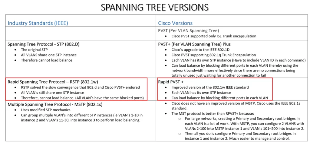
First up is the classic Spanning Tree Protocol, IEEE standard 802.1D. This is the original STP. According to Wikipedia it was originally published in 1990, although the original Spanning Tree was actually created in 1985.
In classic STP, all VLANs share one STP instance, meaning we cannot block different ports in each VLAN to achieve load balancing.
Cisco decided to improve upon this. So Cisco developed Per-VLAN Spanning Tree (PVST), and subsequently PVST+. In PVST (and PVST+) each VLAN has its own STP instance. However, PVST only supported ISL trunk encapsulation, not dot1q. PVST+ on the other hand supports dot1q. Since everyone now uses dot1q for their trunk encapsulation, we can forget about regular PVST. PVST+ is Cisco’s upgrade to 802.1D.
PVST+ supports dot1q but it is still slow like classic STP. In both protocols, the max age timer is 20 seconds, and the listening and learning states are 15 seconds each, so it can take up to 50 seconds to respond to changes in the network. That’s simply not fast enough for modern networks.
This was solved in Rapid Spanning Tree Protocol, IEEE standard 802.1w. It is much faster at converging and adapting to network changes than 802.1D. However, like 802.1D, 802.1w runs only one STP instance, shared by all VLANs. Therefore, it also cannot load balance.
Cisco once again developed an improved version of the industry standard, Rapid Per-VLAN Spanning Tree Plus, or Rapid PVST+. Rapid PVST+ is Cisco’s upgrade to 802.1w, featuring the improved speed of Rapid STP, plus it runs a separate STP instance for each VLAN. Therefore, it can load balance by blocking different ports in each VLAN, just like the previous PVST+.
The final version is Multiple Spanning Tree Protocol, IEEE standard 802.1s. It uses modified RSTP mechanics. The main improvement is that it can group multiple VLANs into different instances, for example, if there are 10 VLANs, VLANs 1 to 5 in instance 1, and VLANs 6 to 10 in instance 2, to perform load balancing. Finally, an industry standard version of STP that allows load balancing.
If you have many VLANs, let’s say 200, in your network, configuring primary and secondary root bridges in each VLAN is a lot of work. However, with MSTP, all you have to do is assign VLANs 1 to 100 to instance 1, and VLANs 101 to 200 to instance 2, and then configure the primary and secondary root bridges for instance 1 and instance 2, so it’s much easier to configure and manage.
Cisco has not developed its own version of MSTP. Cisco devices simply run the industry standard 802.1s. For large networks, it is best to use MSTP. However, for small to medium networks without a huge number of VLANs, Cisco’s Rapid PVST+ is what you will probably run on your switches, and that is the version we will be focusing on. It is also the version that is mentioned in the official CCNA exam topics list.
Cisco’s summary of RSTP:
“RSTP is not a timer-based spanning tree algorithm like 802.1D. Therefore, RSTP offers an improvement over the 30 seconds or more that 802.1D takes to move a link to forwarding. The heart of the protocol is a new bridge-bridge handshake mechanism, which allows ports to move directly to forwarding.”
So that’s the big difference between 802.1D STP and RSTP (802.1w). 802.1D uses long timers to determine when it is safe to move to the next state. RSTP uses a handshake mechanism, which allows switches to actively negotiate with other switches and move ports immediately to the forwarding state if appropriate.
In our present discussion in this document, when we say RSTP and Rapid PVST+ we are talking about the same thing. Also, future references to PVST are really references to PVST+. Cisco’s Rapid PVST+ operates the same as RSTP, but with the addition of a separate instance for each VLAN.
Some similarities between STP and RSTP
*RSTP serves the same purpose as STP, blocking specific ports to prevent Layer 2 loops.
*RSTP elects a root bridge with the same rules as STP. The switch with the lowest Bridge ID becomes the root bridge.
*RSTP also selects root ports with the same rules as STP. The interface with the lowest root cost becomes the root port, with the same tie-breakers, neighbor Bridge ID, and then neighbor port ID.
*RSTP also selects designated ports with the same rules as STP. The interface on the switch with the lowest root cost will become designated and the interface on the other switch in the connection will be non-designated. If there is a tie, the switch with the lowest Bridge ID will set its interface to designated.
Some differences between STP and RSTP
Port costs were updated for Rapid Spanning Tree. Classic Spanning Tree defines port speeds up to 10 Gbps, and faster port speeds are given a cost of 1. To accommodate for faster speeds, RSTP’s cost values were expanded.
| Speed | STP cost | RSTP cost |
| 10 Mbps (Ethernet) | 100 | 2,000,000 |
| 100 Mbps (Fast Ethernet) | 19 | 200,000 |
| 1 Gbps (Gigabit Ethernet) | 4 | 20,000 |
| 10 Gbps (Gigabit Ethernet) | 2 | 2000 |
| 100 Gbps | x | 200 |
| 1 Tbps | x | 20 |
| 10 Tbps | x | 2 |
RSTP port states (discarding, learning, and forwarding)
Let’s first revisit the different port states of classic STP from STP Part 2.
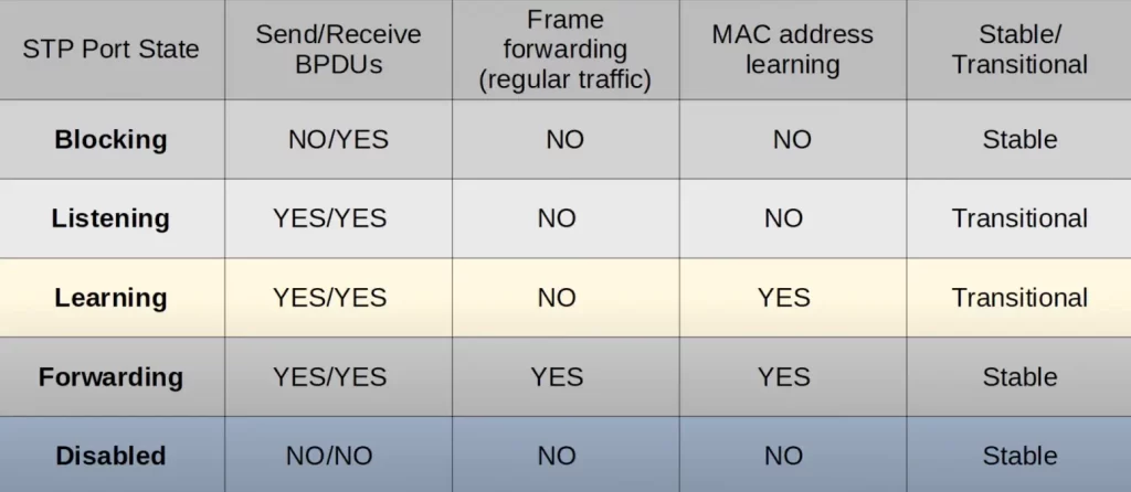
Rapid Spanning Tree simplifies the port states, reducing them to just three.
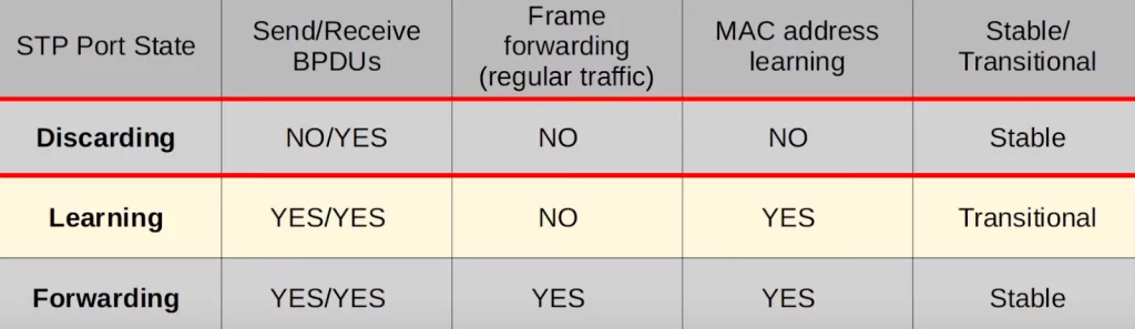
Notice, the blocking and disabled port states were combined into one state, the discarding state, and the listening state was dropped.
If a port is administratively disabled, meaning it has the shutdown command applied to it, it will be in a discarding state in RSTP. This was previously the disabled state. If a port is enabled but blocking traffic to prevent Layer 2 loops, it is also in a discarding state. This was previously the blocking state.
RSTP port roles (alternate and backup)
Are there changes in port roles between classic STP and rapid STP?
Recall from STP Part 1 and STP Part 2, the three original (classic) STP port roles are 1) root ports, 2) designated ports, and 3) non-designated ports.
1) The root port role remains unchanged in RSTP.
The port that is closest to the root bridge, meaning the port with the lowest root cost, becomes the root port.
The root bridge is the only switch that does not have a root port.
So, no change here.
2) The designated port role also remains unchanged in RSTP.
The port on a segment (collision domain) that sends the best BPDU is that segment’s designated port, and there can only be one designated port per segment. The other port on the segment is either a root port or a non-designated port.
3) However, the non-designated port role was divided into two separate roles in RSTP: the alternate port role and the backup port role.
Let’s break down those two roles.
RSTP alternate port role
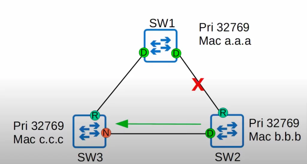
The RSTP alternate port role is a discarding port that receives a superior BPDU from another switch.
In our topology here, SW1 is the root bridge. When BPDUs are sent in this topology, SW3 receives a superior BPDU from SW2. It is superior because the Bridge ID of SW2 is lower than SW3. So SW2’s interface is designated, and SW3’s is an alternate port.
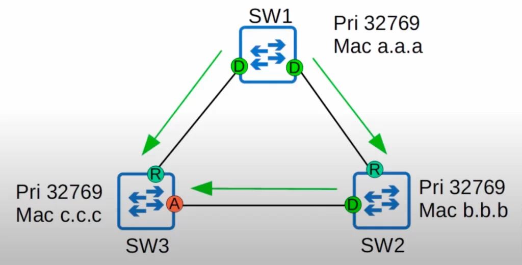
An alternate port basically functions as a backup to the root port.
If SW3’s root port fails, SW3’s alternate port is ready to immediately become the root port, with no transitional states.
This immediate move to forwarding state functions like a classic STP optional feature called UplinkFast. Because UplinkFast is built into RSTP, you do not need to activate UplinkFast when using RSTP/Rapid PVST+.
The RSTP BackboneFast functionality
UplinkFast and BackboneFast are STP optional features that were incorporated into RSTP. Neither of these STP optional features are on the CCNA exam topics list so you don’t have to learn them in depth, but you may still want to learn about their general functionality because they are part of RSTP.
*BackboneFast functionality: let’s say SW2’s root port is cut off, so it stops receiving BPDUs from the root bridge (SW1). It will then assume it is the root bridge, so it will send its own BPDUs to SW3. However, SW3 is now receiving BPDUs from both SW1 and SW2, but SW2’s BPDUs are inferior, they have a higher Bridge ID.
Without this BackboneFast functionality, SW3 would just ignore these BPDUs from SW2 until its non-designated port, in classic STP, finally changes to a forwarding state and forwards the superior BPDUs to SW2, which then accepts SW1 as its root bridge again.
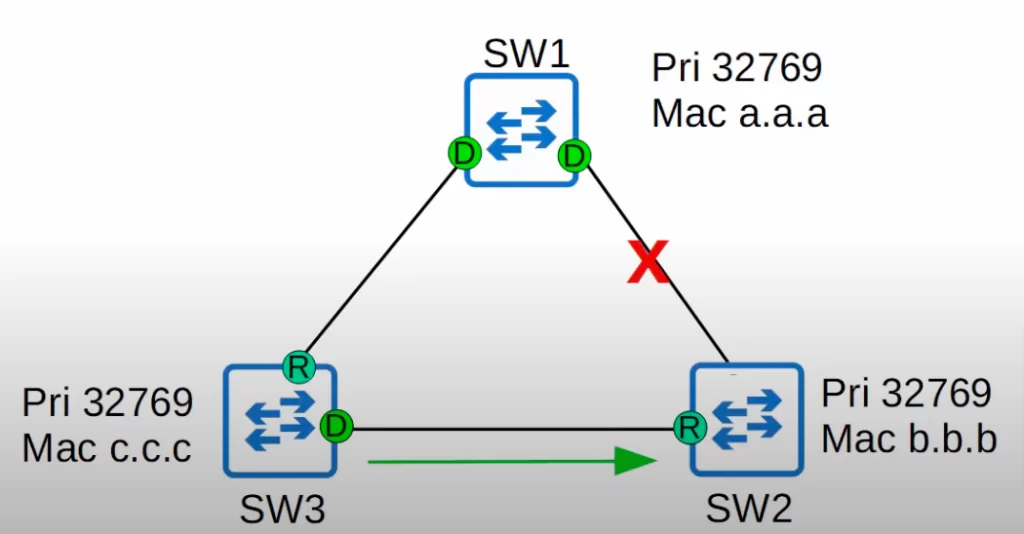
*However, BackboneFast allows SW3 to expire the max age timer on that interface and rapidly forward the superior BPDUs to SW2.
*This functionality is built into RSTP, so it does not need to be configured.
UplinkFast/BackboneFast summary
*UplinkFast and BackboneFast are two optional features in classic STP. They must be configured to operate on the switch, but it’s not necessary to know how to configure them for the CCNA.
*Both features are built into RSTP, so if the switch is running RSTP, you do not have to configure them. They operate by default on all switches running RSTP.
*You do not need to have a detailed understanding of UplinkFast and BackboneFast for the CCNA. But know their names and their basic purpose, which is to help blocking or discarding ports move to forwarding without delay.
Okay, after that little detour…
RSTP backup port role
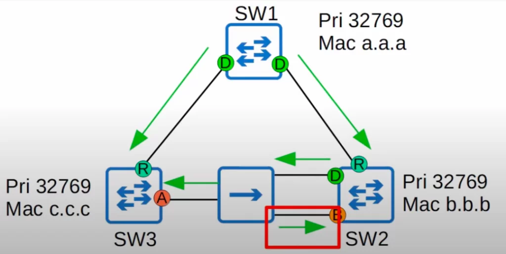
*The RSTP backup port role is a discarding port that receives a superior BPDU from another interface on the same switch.
*This only happens when two interfaces are connected to the same collision domain via a hub.
Notice there is now an Ethernet hub connected between SW2 and SW3. When BPDUs are sent in this network, the BPDU sent out of SW2’s designated port is flooded by the hub, and SW2 ends up receiving that same BPDU on a different interface.
*However, hubs are not used in modern networks, so probably you will not encounter an RSTP backup port, but it’s still something you should know.
Hubs do not participate in Spanning Tree. Hubs are not sophisticated enough to use Spanning Tree, so they just flood all frames they receive.
*RSTP backup ports function as a backup for a designated port. If SW2’s designated port fails, its backup port immediately begins forwarding traffic as a designated port. The switch will choose the port with the lowest port ID as the designated port. The other port will be the backup port.
*See Quiz question 1
RSTP configuration/verification in CLI
Let’s look at the CLI. We are on SW3.
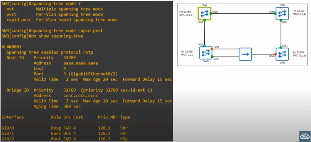
As we saw in STP Part 1, three STP modes can run on a Cisco switch, MST, PVST, and Rapid PVST. Rapid PVST is the default on modern Cisco switches, so you probably will not have to use this command. But let’s enter rapid-pvst mode to make sure it runs in Rapid PVST mode. We then use show spanning-tree to confirm.
Notice it says “Spanning tree enabled protocol rstp.” Previously when we were using classic STP, it said “ieee.” Now it says “rstp.” Although it says rstp, this is in fact Cisco’s Rapid PVST+ running.
There is another difference to point out. As shown in the above network diagram, SW3’s G0/1 interface has the backup role. The status in the CLI output is still listed as BLK (i.e., blocking), although this state is actually called discarding in Rapid STP.
We use the show spanning-tree command on SW4 too.
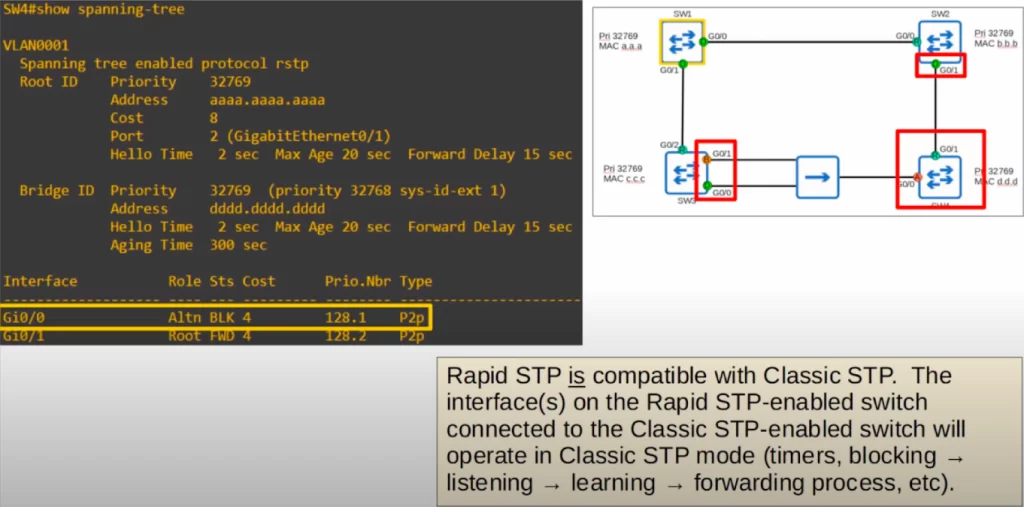
As shown in the network diagram, SW4’s G0/0 interface is an “Altn” (i.e., alternate) port. Again this command lists the status as blocking, but remember the Rapid STP name for this state is actually discarding.
Note, if you have an old switch that does not run Rapid STP, you can still use it in a network of Rapid STP-enabled switches. The switches will adjust the operation of those specific interfaces to match the slower switch.
In the above network diagram, if SW4 was running classic STP, SW2 and SW3 would make the interfaces in the red boxes run in classic STP mode, but their interfaces connected to SW1 would remain in Rapid STP mode.
RSTP BPDU (Wireshark packet capture)
Let’s look at the updated BPDU for RSTP. On the left is the classic STP BPDU. On the right is the Rapid STP BPDU. Most of the BPDU remains unchanged, but there are some differences.
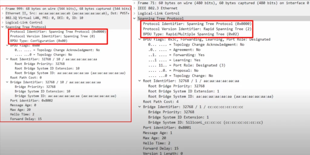
First, notice that the classic Spanning Tree has a protocol version of 0, whereas the RSTP BPDU has a protocol version of 2. Remember these version numbers for the CCNA exam. Note the BPDU types are also 0 and 2 respectively.
The next difference is that classic STP BPDU uses only two bits of the BPDU flags, the 1st bit and the 8th bit, while the Rapid STP BPDU uses all 8 bits. These flags are used in the negotiation process that allows Rapid STP to converge much faster than classic STP.
There is one more major difference. In classic STP, only the root bridge originated BPDUs, the other switches just forwarded the BPDUs they received. In Rapid STP, all switches originate and send their own BPDUs from their designated ports.
Let’s go through a few other differences.
*First, all switches running Rapid STP send their own BPDUs every 2 seconds hello time.
*Switches running Rapid STP also age the BPDU information much more quickly. In classic STP, a switch waits 10 hello intervals, which is 20 seconds. In Rapid STP, a switch considers a neighbor lost if it misses 3 BPDUs, which is 6 seconds. It will then flush, meaning delete, all MAC addresses learned on that interface. Because the neighbor is down, the switch knows it cannot reach anything through that interface any more.
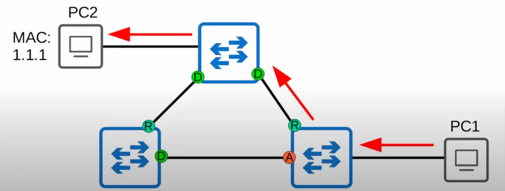
For example, in this network traffic from PC1 to PC2 usually follows the shown path (follow the red arrows).
What if the connection marked by a red X in the diagram below is cut off? The switch with the thought bubble will think, “I can’t reach this neighbor anymore. I’ll clear all entries for this interface from my MAC table”. And the switch’s other interface will become the root port.
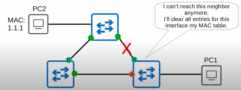
Then, if PC1 wants to send traffic to PC2 again, it will go through the normal process of flooding until it learns the MAC address on the new interface, and traffic will flow through the other switch (the opposite switch on the same horizontal plane).
RSTP link types (edge, point-to-point, and shared)
*RSTP distinguishes between three different link types: edge, point-to-point, and shared.
RSTP link types are used to categorize the ports on a switch that are participating in RSTP.
RSTP link types are types of port links, not types of ports. A port link is a connection between two ports on different switches. That said, edge is a port type.
Basically, the point-to-point and shared link types just distinguish between full and half-duplex connections, and the edge type is a port that uses PortFast.
*The first link type is edge.
An edge port is a port at the edge of the network, meaning it is connected to end hosts. An edge port is a port on a switch that connects directly to a device on the network such as a computer or a server. Edge ports are not connected to any other switches, so they do not participate in the STP. This means that edge ports can be placed in the forwarding state immediately, without having to go through the listening and learning states first. This can improve network performance, as it allows traffic to flow through edge ports more quickly.
Because there is no risk of creating a loop, edge ports can move straight to the forwarding state without the negotiation process.
Edge ports function like a classic STP port with PortFast enabled. You configure an edge port simply by enabling portfast on the port. So, PortFast and an RSTP edge port are really the same thing. Here is the command, just like in classic STP.
SW1(config-if)#spanning-tree portfast
*The next link type is point-to-point.
A point-to-point link is used for direct connections between two switches. The ports connect directly to another switch. Because the ports connect to a switch, not a hub, the ports function in full-duplex mode.
You do not need to configure the interface as point-to-point, the switch should be able to detect that it is connected directly to another switch and will operate in full-duplex as a point-to-point port.
However, you can use this command if you want to explicitly configure the point-to-point link type:
SW1(config-if)#spanning-tree link-type point-to-point
*The third link type is shared.
You will probably not use this link type at all in your networking career. This is a connection to a hub. These connections must operate in half-duplex to avoid collisions.
Shared ports connect to another switch via a hub. Due to the nature of hubs and the likelihood of collisions, these links must function in half duplex.
Once again, you do not need to configure the interface in shared mode, the switch will detect it.
However, to manually configure it, use this command:
SW1(config-if)#spanning-tree link-type shared
Command review
SW(config-if)#spanning-tree portfast
→to configure an edge port by enabling portfast on the port
SW(config-if)#spanning-tree link-type point-to-point
→to configure the point-to-point link type
SW(config-if)#spanning-tree link-type shared
→to configure the interface in shared mode
Free CCNA | Rapid STP | Day 22 Lab – Notes
Key learnings
*Comparison of STP versions (standard vs Cisco)
*Rapid PVST+
All the information covered about Rapid PVST+ applies to the industry standard RSTP. RSTP is an evolution of classic STP. Instead of using timers, it uses a negotiation process to allow it to rapidly move the necessary ports to a forwarding state, and rapidly adjust to changes in the network topology. We did not mention any specifics of the negotiation process, that level of depth is not necessary for the CCNA.
>RSTP port states (discarding, learning, and forwarding).
There are three port states in RSTP. Discarding, learning, and forwarding. The listening state was deemed unnecessary, and in fact the learning state is often skipped due to the built-in features of Rapid STP, like UplinkFast and BackboneFast.
>RSTP port roles (alternate and backup).
We discussed four RSTP port roles. Root and designated ports are the same as in classic STP, but RSTP distinguishes between two types of ports in the discarding state. Alternate ports are discarding ports which receive a superior BPDU from another switch, this is the usual case. Backup ports, on the other hand, receive a superior BPDU from an interface on the same switch. This only occurs if connected to a hub, which is a situation you will probably never encounter, as hubs are no longer used.
>STP optional features built into the RSTP (UplinkFast, BackboneFast, and PortFast).
We discussed some optional features of classic STP which are built into RSTP. First we saw UplinkFast and BackboneFast, but PortFast is also built in, through the edge port function. You have to know PortFast for the CCNA. You do not need a detailed understanding of UplinkFast and BackboneFast for the CCNA.
>RSTP BPDU (sent by all switches, not just the root bridge).
In RSTP all switches send BPDUs, not just the root bridge. The protocol version in an RSTP BPDU is 2, whereas in classic STP it’s 0.
>RSTP link types (edge, point-to-point, and shared).
Edge ports are connected to end hosts, and you configure an edge port by enabling PortFast on the interface. Point-to-point means it is connected directly to another switch, and shared means it is connected to a hub, and must use half-duplex.
Practice quiz questions
Quiz question 1
Identify the root bridge and the RSTP port role of each switch interface in this network.
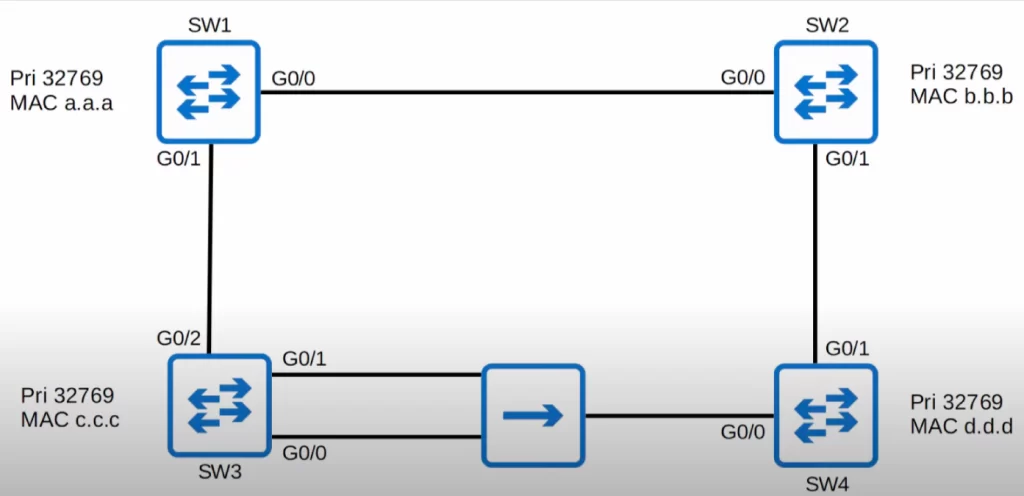
The root bridge is SW1. SW1 is elected as the root because all switches have the same priority and SW1 has the lowest MAC address. SW1’s interfaces are designated ports. All ports on the root bridge become designated ports, in a forwarding state.
Here are the root ports for each switch. SW2’s and SW3’s root ports are obvious, they have the lowest root cost. SW2’s root port is G0/0. SW3’s root port is G0/2.
How about SW4’s root port? The hub does not participate in STP so it does not add any cost to the BPDU. SW4’s root port is G0/1 because the neighbor Bridge ID is lower via SW4’s G0/1, because SW2 has a lower MAC address than SW3.
SW2’s G0/1 connected to SW4’s G0/1 becomes designated. Ports across from (connected to) the root port are always designated ports.

What about the connection between SW3 and SW4? First of all, which switch sets its interface to designated? Every collision domain has a single Spanning Tree designated port. The switch forming a link with the switch with the designated port will make its port non-designated (discarding).
SW3 has a lower root cost, so one of its interfaces will be the designated port. SW3’s G0/0 has a lower port ID than its (SW3’s) G0/1, so SW3’s G0/0 will be the designated port in this collision domain.
SW3’s G0/1 receives the superior BPDU, with the lower port ID, from the same switch, so it is a backup port.
SW4’s G0/0 receives the superior BPDU from a different switch, so it is an alternate port.
Quiz question 2
Which IEEE 802.1D optional features were built into the IEEE 802.1w standard, and allow ports to move rapidly to the forwarding state? Select three.
A. Root guard
B. PortFast
C. BPDU guard
D. UplinkFast
E. BackboneFast
F. Loop guard
G. RootFast.
The answers are B (PortFast), D (UplinkFast), and E (BackboneFast). B, PortFast, allows edge ports to move rapidly to the forwarding state. D, UplinkFast, and E, BackboneFast, allow ports to move rapidly to forwarding in certain cases of interface failure.
You can find two more practice questions for this lesson (plus a bonus one) in Jeremy’s Rapid Spanning Tree Protocol (Day 22) video, cited below.
Key references
Note: The resources cited below (in the “Key references” section of this document) are the main source of knowledge for these study notes/this lesson, unless stated otherwise.
Free CCNA | Rapid Spanning Tree Protocol | Day 22 | CCNA 200-301 Complete Course
Free CCNA | Rapid STP | Day 22 Lab | CCNA 200-301 Complete Course
Other references/resources
Related content
Classic Spanning Tree port states
Compliance frameworks and industry standards
How data flow through the Internet
How to break into information security
IT career paths – everything you need to know
Job roles in IT and cybersecurity
Network security risk mitigation best practices
STP root bridge election and root port selection
The GRC approach to managing cybersecurity
The penetration testing process
The Security Operations Center (SOC) career path
Back to DTI Courses


