This post covers two Cisco proprietary protocols, DTP (dynamic trunking protocol) and VTP (VLAN trunking protocol). This post looks at the basic characteristics and functions as well as the configuration and verification of DTP and VTP on Cisco switches.
DTP allows Cisco switches to dynamically determine (negotiate) the status of their switchports to be either access ports or trunk ports without manually configuring them. VTP allows us to configure VLANs on switches that operate as central VTP servers, which then advertise their VLAN database. VTP client switches then synchronize their VLAN database to the advertised VLAN database, saving the network admin the trouble of configuring VLANs on every single switch in the network.
DTP and VTP are not (any longer) on the CCNA exam topics list, but they have real-world relevance and they may still show up on the CCNA exam. They reemerge in the CCNP ENCOR 350-401 exam topics list, in topic 3.1 Layer 2 Infrastructure. Subtopic 3.1.a says you must be able to “Troubleshoot static and dynamic 802.1q trunking protocols”. This post is part of my CCNA 200-301 study notes.
- DTP (Dynamic Trunking Protocol) introduction
- DTP configuration (DTP modes)
- DTP modes chart
- Disabling DTP
- Trunk encapsulation negotiation via DTP
- VTP (VLAN Trunking Protocol) introduction
- VTP modes (server, client, transparent)
- How VTP works
- VTP risk
- VTP functionality configurations
- VTP version configuration
- Command review
- Key references
You may also be interested in CCNA 200-301 study notes.
DTP (Dynamic Trunking Protocol) introduction
DTP allows Cisco switches to dynamically determine their interface status (access or trunk) without manual configuration.
We manually configure switchports using either SWITCHPORT MODE ACCESS or SWITCHPORT MODE TRUNK. If we use DTP, we do not need to enter these commands.
DTP is enabled by default on all Cisco switch interfaces. Two Cisco switches (Catalyst 2960, 3560, 3750, 3850, 4500, 6500) connected together can form a trunk, otherwise the interface will automatically be an access port.
DTP can be exploited by attackers. For security reasons, it is recommended that you disable DTP on all switchports and manually configure them as access or trunk ports.
DTP configuration (DTP modes)
The DTP configuration command sets trunking mode to dynamically negotiate access or trunk mode. DTP operates in two modes: dynamic desirable and dynamic auto.
SW(config-if)#switchport mode dynamic {auto | desirable}
A switchport in dynamic desirable mode will actively try to form a trunk with other Cisco switches. It will form a trunk if connected to another switchport in the following modes: switchport mode trunk, switchport mode dynamic desirable, and switchport mode dynamic auto.
Here are the scenarios.
1) SW1’s G0/0 interface is in dynamic desirable mode. SW2’s G0/0 interface is manually configured as a trunk.
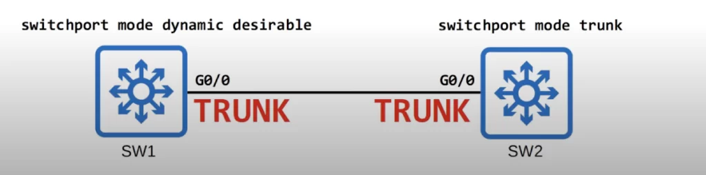
The two switches will both agree to operate as trunks.
This is probably a good time to introduce the show interfaces switchport command. It is used to display detailed information about the switchports configured for Layer 2 switching. It provides information on various aspects of the switchport configuration, including:
- Mode: Whether the port is configured as an access port or a trunk port.
- VLAN: For access ports, it shows the VLAN the port is assigned to.
- Speed and Duplex: The configured speed (e.g., 100 Mbps, 1 Gbps) and duplex mode (full or half duplex) of the port.
- Link: Shows whether the physical connection on the port is up or down.
- Auto-Negotiation: Whether auto-negotiation is enabled for speed and duplex.
- Other: Depending on the switch model and IOS version, it can also display information about security settings (e.g., port security), trunking encapsulation (e.g., dot1q), and other switchport specific configurations.
In summary, this command is a vital tool for network administrators to:
- Verify switchport configuration and ensure ports are set up as intended (access or trunk).
- Troubleshoot connectivity issues by checking link status and other port settings.
- Monitor switchport use and identify potential configuration errors.
The show interfaces switchport command can be used with additional arguments to filter the output for specific interfaces or modules. For a more detailed view of the switchport configuration, you can use the show running-config interface interface-number command, which displays the complete configuration for the specified interface.
Let’s use the SHOW INTERFACES SWITCHPORT command to check the current switchport configuration status on SW1 and SW2, beginning with SW1.

The switchport is enabled (because it is a L2 port, as opposed to a routed port).
The administrative mode is dynamic desirable. Administrative mode is what we actually configured on the interface.
The operational mode is trunk. Operational mode displays whether it is a trunk or access port.
On SW2, both the administrative mode and operational mode are trunk.
Because SW2’s interface is a trunk, the two switches agreed to operate as trunks.
2) Both interfaces are configured in dynamic desirable mode. They will both form a trunk.
3) SW1 is configured as dynamic desirable mode. SW2’s interface is configured in dynamic auto mode. They will both form a trunk.
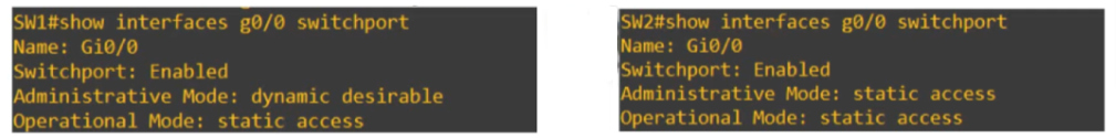
4) SW1 is configured as dynamic desirable mode. SW2’s interface is manually configured as an access port with the SWITCHPORT MODE ACCESS command.
SW1 tries to actively form a trunk, but since SW2 is manually configured in access mode, a trunk will not form. Both ports will operate as access ports in the default VLAN, VLAN 1.
The output of SHOW INTERFACES SWITCHPORT on SW1 and SW2 now shows an operational mode of static access, meaning, an access port that belongs to a single VLAN. There are also dynamic access ports in which a server automatically assigns the VLAN depending on the MAC address of the connected device. But this is out of the scope of the CCNA.
To summarize, a switchport in dynamic desirable mode will use DTP negotiation to form a trunk if the connected interface on the other device is in trunk, dynamic desirable, or dynamic auto mode. If the other interface is in access mode, it will not form a trunk. It will be an access port.
Next, let’s go over the possible scenarios when a switchport in dynamic auto mode is connected to an interface on another switch in trunk, dynamic desirable, and dynamic auto modes.
A switchport in dynamic auto mode will not actively try to form a trunk with other Cisco switches, however it will form a trunk if the switch connected to it is actively trying to form a trunk. It will form a trunk with a switchport in the following modes: switchport mode trunk or switchport mode dynamic desirable.
1) switchport mode dynamic auto + switchport mode trunk: DTP negotiation will result in a trunk link.
2) switchport mode dynamic auto + switchport mode dynamic desirable: They will both form a trunk.
3) Two switchports in dynamic auto mode: neither is actively trying to form a trunk, so both operate as access ports in the default VLAN, VLAN1. And they both have the same output for the SHOW INTERFACES SWITCHPORT command, administrative mode of dynamic auto and operational mode of static access.
4) Dynamic auto and access mode. Both interfaces operate as access ports.
Finally, what happens when a manually configured trunk is connected to a manually configured access port? Since both interfaces are manually configured, they are forced to operate mismatched in trunk and access modes. This configuration does not work – traffic will not pass between these switches.
DTP modes chart
The following chart summarizes the resulting operational mode given two administrative modes.
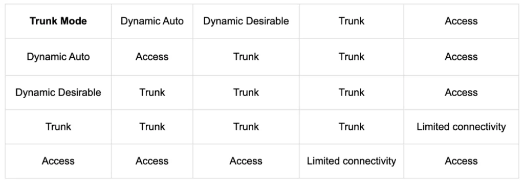
For example, a switchport in dynamic desirable mode will form a trunk with an interface in any administrative mode except access.
Note, DTP will not form a trunk with a router or a PC. The switchport will be in access mode. If we want to configure router on a stick, we have to manually configure the interface connected to the router as a trunk.
Disabling DTP
DTP negotiation is enabled by default on interfaces that are configured as trunks. An interface manually configured as a trunk will send DTP frames to the connected device attempting to establish a trunk.
On older switches, the default administrative mode is switchport mode dynamic desirable. On newer switchers, the default administrative mode is switchport mode dynamic auto.
DTP negotiation can be disabled on an interface with the command switchport nonegotiate. The interface will stop sending DTP negotiation frames.
Configuring an access port with switchport mode access also disables DTP negotiation on an interface. The interface will also stop sending DTP frames.
However, manually configuring an interface in trunk mode does not stop it from sending DTP frames, unless the SWITCHPORT NONEGOTIATE command is issued.
Trunk encapsulation negotiation via DTP
In switches that support both dot1q and ISL trunk encapsulation options, DTP can be used to negotiate the encapsulation they will use. This negotiation is enabled by default. The default trunk encapsulation mode is switchport trunk encapsulation negotiate.
On a switch that supports both dot1q and ISL encapsulation, we must change the encapsulation mode to dot1q if we want to configure a trunk interface with the dot1q encapsulation mode – we cannot leave the setting in negotiate mode. ISL is favored over dot1q, so if both switches support ISL it will be selected.
The DTP frames that DTP uses to negotiate when using ISL are sent in VLAN 1, the default native VLAN. The DTP frames that DTP uses to negotiate when using dot1q are sent in the native VLAN. So unless the native VLAN is changed, the DTP frames will be sent in VLAN 1 in both cases.
To illustrate this negotiation of trunking encapsulation, here is a little more of the output from SHOW INTERFACES SWITCHPORT. The interfaces on both switches are set to dynamic desirable mode so they would form a trunk. The default trunking encapsulation mode of negotiate results in an operational trunking encapsulation of ISL.
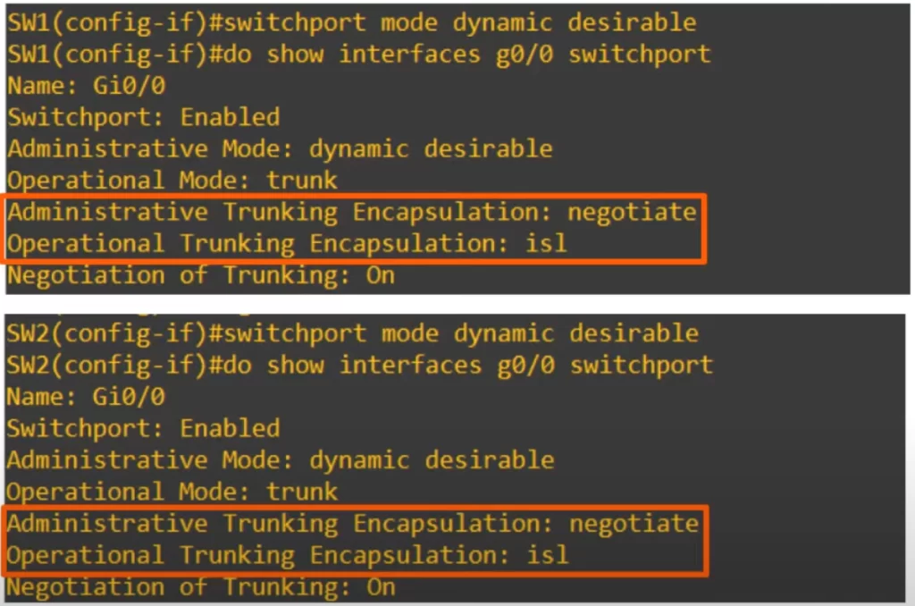
The field “negotiation of trunking” shows whether DTP is enabled (whether the interface is sending DTP frames or not). If the interface is in dynamic desirable, dynamic auto, or trunk mode, this will be on. If it’s in access mode or if you use the switchport nonegotiate command, this will be off.
VTP (VLAN Trunking Protocol) introduction
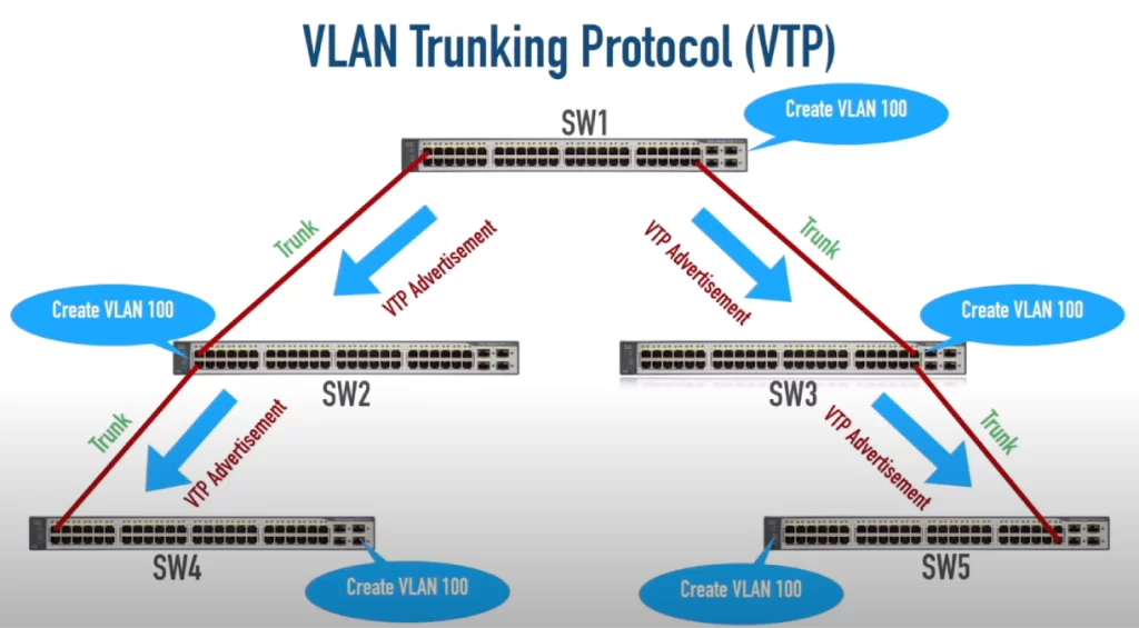
VTP allows us to configure VLANs on a central server switch, and other switches called VTP clients will sync their VLAN database to the server. VTP allows us to create, modify, or delete a VLAN on one switch and have that change propagated throughout our switched infrastructure, saving us the trouble of having to manually configure each switch individually.
If we create VLAN 100 on SW1 and VTP is configured, SW1 can send VTP advertisements over its trunk links down to SW2 and SW3 and they will update their VLAN database and create VLAN 100. Then SW2 and SW3 on their part will forward the VTP advertisements down to switches SW4 and SW5 and they too will have VLAN 100 created in their VLAN database.
VTP is designed for large networks with many VLANs, so that you don’t have to configure each VLAN on every single switch.
However, like DTP it is rarely used, and it is recommended that you do not use it because if not appropriately configured, VTP poses a potentially big risk to the operations of a network.
There are three versions of VTP, 1, 2 and 3. Most modern Cisco switches support all three, but older switches might only support 1 and 2.
VTP modes (server, client, transparent)
A switch running VTP can operate in three different VTP modes: server, client, and transparent. Cisco switches operate in VTP server mode by default.
VTP servers
- can add, modify, and delete VLANs.
- store the VLAN database in non-volatile RAM, also called NVRAM, so the VLAN database is saved even if the switch is turned off or reloaded.
- will increase the revision number every time a VLAN is added, modified, or deleted. VTP uses the revision number to determine the newest version of the VLAN database, the version that the switches will sync to.
- will advertise the latest version of the VLAN database on trunk interfaces, and the VTP clients will sync their VLAN database to it. VTP advertisements are only sent on trunk ports, not on access ports.
- also function as VTP clients. A VTP server will sync to another VTP server with a higher revision number, because the highest revision number is considered the newest and most accurate version of the VLAN database.
VTP clients
- cannot add, modify, or delete VLANs. If you try to add, modify, or delete a VLAN in the CLI, the command will be rejected.
- do not store the VLAN database in NVRAM, though in VTPv3, they do.
- will sync their VLAN database to the server with the highest revision number in their VTP domain.
- will advertise their VLAN database, and forward VLAN advertisements to other clients over their trunk ports.
VTP transparent
Switches in VTP transparent mode do not participate in the VTP domain – they do not sync their VLAN database to the VTP server.
A switch in VTP transparent mode maintains its own independent VLAN database in NVRAM. It can add, modify, or delete VLANs, but it will not advertise its VLAN database to other switches.
Although a switch in VTP transparent mode will not sync its VLAN database, it will forward VTP advertisements over its trunk ports, if the VTP advertisement is in the same domain as it.
VTP modes key characteristics summary
| Descriptor | Server | Client | Transparent |
| Creates, modifies, deletes LANs | T | F | T |
| Synchronizes VTP information | T | T | F |
| Originates VTP advertisements | T | T | F |
| Forwards VTP advertisements | T | T | T |
| Stores VLAN information in NVRAM | T | T for VTPv3 | T |
How VTP works
The interfaces of these four switches are configured as trunks, so they will send and receive VTP advertisements between each other.
Here is the output of the SHOW VTP STATUS command on SW1. All these switches have the default configuration, so their output will be very similar.
Let’s look at some of the output fields.
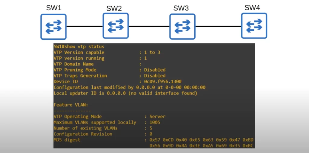
Notice that there is no domain name. By default the domain name is null (no domain name). If we want VTP to sync among these switches, we have to configure them all with the same VTP domain name.
Notice the default VTP operating mode of server.
The maximum number of VLANs supported locally is 1005. VTP versions 1 and 2 do not support the extended VLAN range of 1006 to 4094, but version 3 does.
The number of existing VLANs is 5, those are the VLANs that exist by default on the switch, VLANs 1, 1002, 1003, 1004, and 1005.
Finally, notice the configuration revision number. It’s 0 at the moment. If a VLAN is added, modified, or deleted, the revision number will increase to 1 and SW1 will advertise this to VTP clients in the same domain. SW1 will also update its own VLAN database if it receives a VTP advertisement with a higher revision number.
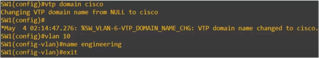
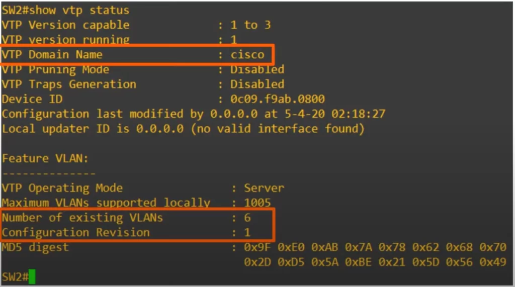
The command VTP DOMAIN CISCO was used to change SW1’s VTP domain name to cisco. And VLAN 10 was created and then named engineering.
The output of SHOW VTP STATUS shows the revision number has increased from 0 to 1, the number of existing VLANs has increased from 5 to 6, and the VTP domain name has changed to cisco.
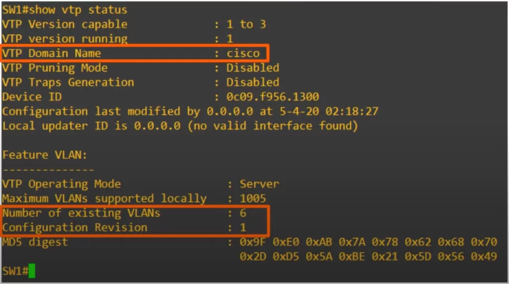
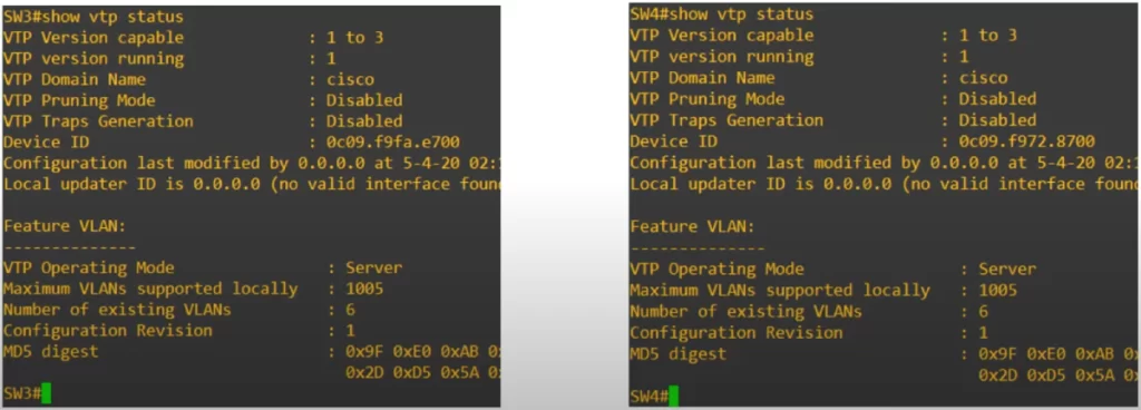
Let’s check on the other switches to see if these configuration changes have propagated.
SW2 has changed its domain name to cisco, and it has updated its VLAN database to match SW1’s, with a revision number of 1 and existing VLANs of 6.
SW2 automatically joined the domain cisco. If a switch with no VTP domain receives a VTP advertisement with a VTP domain name, it will automatically join that VTP domain.
Recall, if a switch receives a VTP advertisement in the same VTP domain with a higher revision number, it will update its VLAN database to match.
Using the SHOW VLAN BRIEF on SW2 now will show that VLAN 10 engineering was added to the device’s configuration files.
As you can see here, the VTP advertisements were passed along to SW3 and SW4, and they joined the domain cisco and updated their VLAN database as well.
VTP risk
VTP can be a great time-saver, but there’s also a lurking danger. Connecting an old switch with a higher VTP revision number to a network (and the VTP domain name matches) will cause all switches in the domain to sync their VLAN database to the old switch. A lot of hosts in the network might then instantly lose connectivity, as the previously configured VLANs would suddenly disappear and get replaced with a totally different VTP database.
Let’s say the VTP domain cisco has a revision of 5, and VLANs 1, 10, 20, 30, and 40 configured. Then an old company switch, which has a revision number of 50 and VLANs 1, 99, and 220 configured, is added to the network. The old switch will send VTP advertisements which will be propagated throughout the VTP domain with a revision number of 50.
All switches within the domain cisco will update their VLAN database to match, and all hosts in VLANs 10, 20, 30, and 40 will suddenly lose connectivity.
VTP functionality configurations
Let’s compare the functionality of server, client, and transparent mode switches.
Recall, VTP clients cannot add, modify, or delete VLANs.
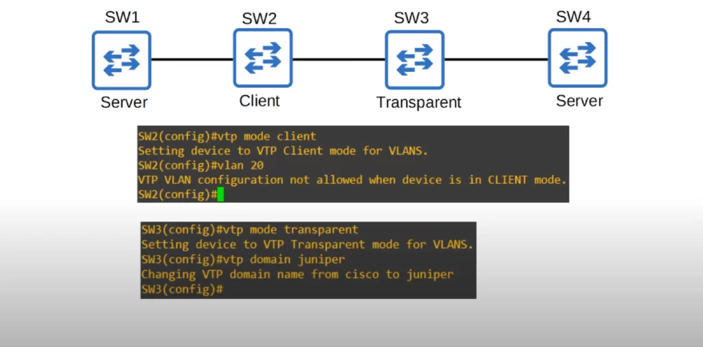
We set SW2 to client mode with the command VTP MODE CLIENT and then tried to create VLAN 20 on the switch. As expected, the command was rejected.
Recall, a switch in transparent mode will not sync its own VLAN database to the server’s, but will still forward VTP advertisements to switches in the same domain. A transparent mode switch will not forward VTP advertisements to switches in a different domain.
We set SW3 to transparent mode with VTP MODE TRANSPARENT, and changed the domain name on SW3 to juniper using the command VTP DOMAIN JUNIPER.
Now we can expect that VLAN configuration changes on SW1 or SW2 will not be synced to by SW3. Further, we expect such configuration changes not to propagate to SW4.
Let’s check.
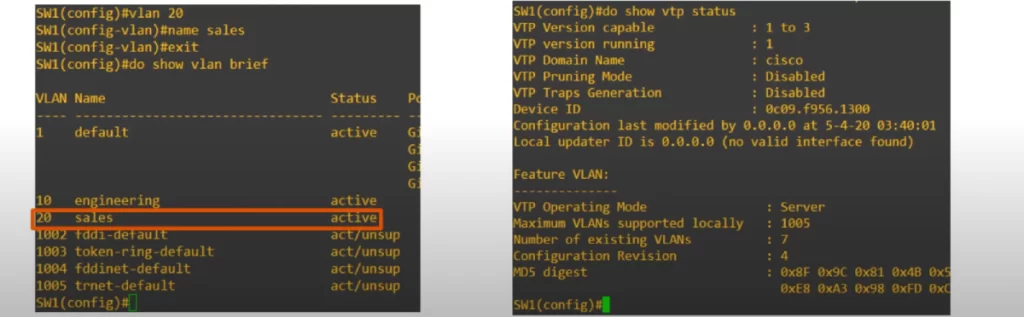
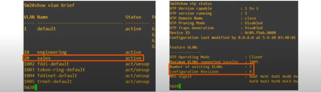
On SW1, VLAN 20 sales was created and it appears in the output of show vlan brief.
Using show vtp status on SW1 shows the configuration revision number has increased to 4 (it should be 2. The number 4 appears because a few other changes not relevant to our discussion here were made and raised the number to 4). As expected, the number of existing VLANs increased from 6 to 7.
The latter configuration should be propagated to SW2. And it was.
As you can see, the VTP client SW2 has added VLAN 20 to its VLAN database, and it now has the same revision number, 4, and the same number of VLANs, 7.
As expected, on the transparent switch SW3, VLAN 20 was not added. And now it has a revision number of 0.
Changing the VTP domain to an unused domain will reset the revision number to 0. Changing the VTP mode to transparent will also reset the revision number to 0.
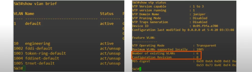
If you intend to introduce an old switch into a network that uses VTP, reset the revision number first with one of these methods so that an old/new switch does not overwrite the network’s VLAN configurations.
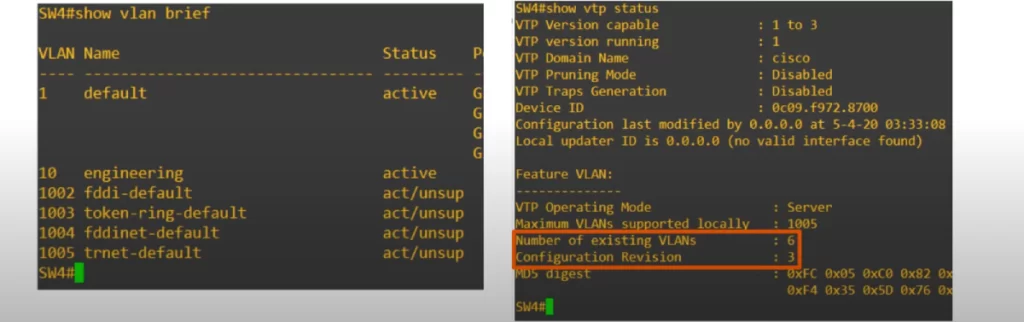
Now let’s check if SW4 added VLAN 20 to its VLAN database. As expected, SW4 does not have VLAN 20, and it is still on revision number 3.
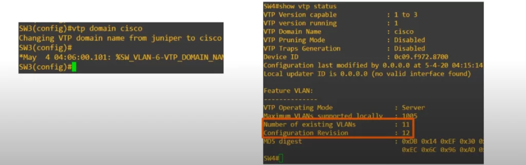
To make SW3 start forwarding the VTP advertisements to SW4, we need to change the VTP domain on SW3 back to cisco.
Let’s see.
We changed the VTP domain on SW3 back to cisco, and created some new VLANs on SW1 to increase the revision number and send more advertisements.
Now you can see that SW3 did indeed forward the advertisements to SW4, and SW4 synced its VLAN database to SW1 and SW2.
VTP version configuration
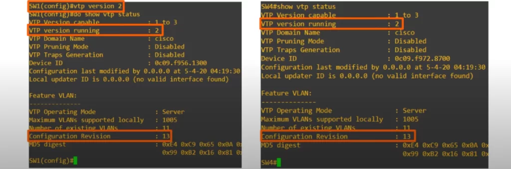
To change the VTP version, use the VTP VERSION command.
Changing the VTP version increases the revision number, and the new revision number will be advertised to other switches in the same VTP domain. Other VTP clients will then sync and start operating in version 2 as well.
For example, here is SW4. It is now running version 2 and has a revision number of 13, just like SW1.
As for the difference between VTP version 1 and version 2, here is a quote directly from Cisco:
“VTP V2 is not much different than VTP V1. The major difference is that VTP V2 introduces support for Token Ring VLANs. If you use Token Ring VLANs, you must enable VTP V2. Otherwise, there is no reason to use VTP V2.”
As for version 3, it has quite a few differences and new features, but it’s beyond the scope of the CCNA.
Command review
1. DTP (Dynamic Trunking Protocol)
SW#show interfaces interface switchport
SW(config-if)#switchport mode dynamic {auto | desirable}
SW(config-if)#switchport nonegotiate
→to disable DTP negotiation. The interface will stop sending DTP negotiation frames
2. VTP (VLAN Trunking Protocol)
SW#show vtp status
SW#show vlan brief
SW(config)#vtp domain domain-name
→to change/set the switch’s VTP domain name
SW(config)#vtp mode {client | transparent}
SW(config)#vtp version version
Key references
Note: The resources cited below (in the “Key references” section of this document) are the main source of knowledge for these study notes/this lesson, unless stated otherwise.
Free CCNA | DTP/VTP | Day 19 | CCNA 200-301 Complete Course
VLAN Trunking Protocol (VTP) – Theory and Configuration (Kevin Wallace Training, LLC)
Related content
Compliance frameworks and industry standards
Configuring access ports on Cisco switches
Configuring trunk ports on Cisco switches
How data flow through the Internet
How to break into information security
IT career paths – everything you need to know
Job roles in IT and cybersecurity
Network security risk mitigation best practices
The GRC approach to managing cybersecurity
The penetration testing process
The Security Operations Center (SOC) career path
Back to DTI Courses


