This post represents Part 3 of 3 of VLANs study notes for the CCNA exam. This lesson covers two main topics. First, we look at two methods of configuring the native VLAN on a router, using the router subinterface, and configuring the IP address on the router’s physical interface. Second, we learn about inter-VLAN routing using Layer 3 switches. We learn how to configure SVIs (switch virtual interfaces) on multilayer switches and how this makes it possible to route between subnets and VLANs without having to send traffic to a router.
Part 2 focuses on configuring trunk ports on Cisco switches and configuring router on a stick (ROAS) for inter-VLAN routing. Part 1 focuses on configuring and verifying default VLANs and access ports on Cisco switches. This post represents Issue 14 of my CCNA 200-301 study notes.
- Native VLAN on a router (ROAS)
- How to configure the native VLAN on a router
- Layer 3 switching/multilayer switching
- Inter-VLAN routing methods – summary
- Inter-VLAN routing via SVIs (Switch Virtual Interfaces)
- SVI configurations
- Command review
- Key learnings
- Key references
You may also be interested in CCNA 200-301 study notes.
Native VLAN on a router (ROAS)
A native VLAN is a special VLAN that is used for untagged traffic on a trunk link. When a switch receives an untagged frame on a trunk link, it will forward the frame to the native VLAN. The native VLAN is configured per trunk port.
The native VLAN feature has a key benefit. Because frames in the native VLAN are not tagged, each frame is smaller in size than a tagged frame (the 4-byte VLAN tag is not included in the frame), which allows the device to send more frames per second.
Let’s see how to use the native VLAN feature on a router when using ROAS for inter-VLAN routing.
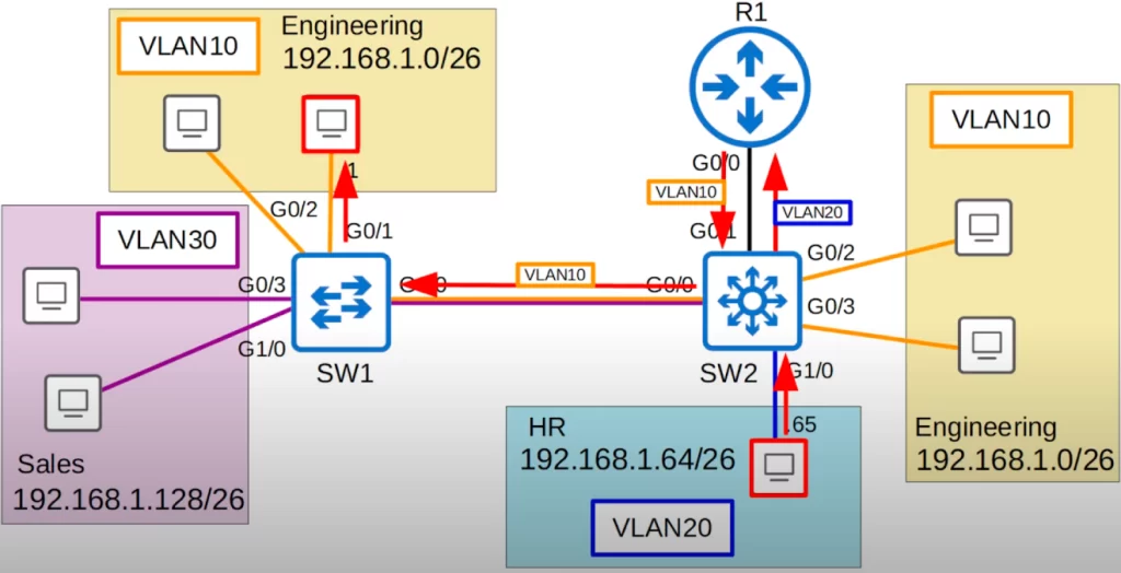
Here is our network diagram from VLANs study notes Part 2.
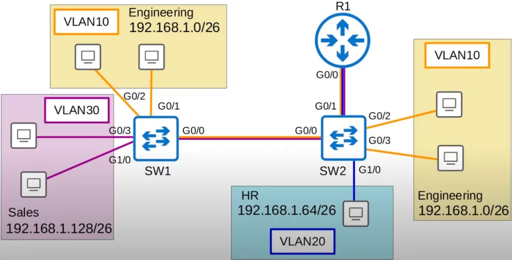
For this demonstration let’s set the native VLAN to VLAN10 on all trunks, i.e., on SW1’s G0/0 interface and SW2’s G0/0 and G0/1 interfaces.
SW1(config)#int g0/0
SW1(config-if)#switchport trunk native vlan 10
SW2(config)#int g0/0
SW2(config-if)#switchport trunk native vlan 10
SW2(config)#int g0/1
SW2(config-if)#switchport trunk native vlan 10
How to configure the native VLAN on a router
There are two methods of configuring the native VLAN on a router. The first method is executed using the encapsulation dot1q command on the router’s subinterface. The second method is configuring the IP address for the native VLAN on the router’s physical interface. In both cases, the native VLAN must be configured identically on both ends of the trunk link, the router and the switch, or traffic will not pass between the router and the switch.
Let’s look at both methods.
>The first method of configuring the native VLAN on a router involves using the router subinterface. On the router subinterface, use the command encapsulation dot1q followed by the VLAN ID (VLAN number) followed by the keyword native.
R1(config)#int g0/0.10
R1(config-subif)#encapsulation dot1q 10 native
This command tells the router that this subinterface (g0/0.10) belongs to the native VLAN (VLAN10) and it will function just like the native VLAN on a switch. The router will assume that untagged frames belong to the native VLAN, and frames sent in the native VLAN will not be tagged.
Note that this is the same topology from VLANs Part 2 (see the above network diagram), so the IP address for the G0/0.10 subinterface is already configured. The only change is that we added native to the encapsulation dot1q command.
Wireshark analysis
Before discussing the second method of configuring the native VLAN on a router, let’s look at a Wireshark capture to demonstrate the native VLAN.
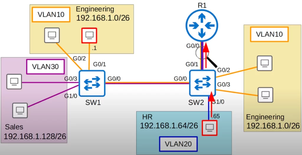
The PC in VLAN20 (192.168.1.65) pings the PC in VLAN10 (192.168.1.1) (the PCs in red boxes).
Let’s use Wireshark to monitor traffic on the connection between SW2 and R1. Wireshark will capture all frames on this connection in both directions.
First let’s look at the Wireshark capture for the ICMP echo request message as it goes from SW2 to R1. The ICMP echo request message will be in VLAN20 and it is being sent to R1 for inter-VLAN routing.
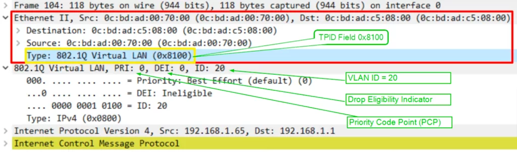
Look at the fields of the Ethernet frame header, extending from “Destination” (under “Ethernet II”) down to the Ethernet Type field (EtherType), “Type: IPv4 (0x0800)”.
Here is a diagram of the Ethernet frame header with the 802.1Q VLAN tag:
Destination MAC address | Source MAC address | 802.1Q Virtual LAN tag | EtherType
The 802.1Q VLAN tag is inserted after the source MAC address field in the Ethernet frame header. The dot1q tag is 4 bytes long. It is composed of the following fields:
- Tag Protocol Identifier (TPID): This is a 2-byte field that identifies the type of tag (IEEE 802.1Q tag or IEEE 802.1ad tag). The value for an 802.1Q tag is 0x8100.
- Tag Control Information (TCI): This is a 2-byte field. TCI is comprised of three fields, PCP (Priority Code Point), DEI (Drop Eligible Indicator), and VID (VLAN ID).
Look at the tag type field, “Type: 802.1Q Virtual LAN (0x8100)”, and notice the hexadecimal value of 8100. When the switch sees this value of 8100, it knows the frame is dot1q-tagged.
The PCP field has a value of 0, so no special priority is given to this frame. The DEI also shows a value of 0, so the frame will not be dropped during times of network congestion. Next is the most important field, the VLAN ID, which is 20, as expected. The PC that sent the ping is in VLAN 20, and it’s not the native VLAN so the frame is tagged as VLAN 20.
“Type: IPv4 (0x0800)” is the Ethernet Type (EtherType) field, which is the last field in the Ethernet header. An EtherType value of 0x0800 indicates that the frame contains an IPv4 datagram. It is indicating that an IPv4 packet is encapsulated. The Ethernet Type field indicates the Layer 3 protocol used in the encapsulated packet, which is almost always Internet Protocol, IPv4 or IPv6. However, sometimes this is a length field, indicating the length of the encapsulated data, depending on the version of Ethernet.
After the Type field, after the frame header section, there is the packet payload field (the “Internet Protocol Version 4” field), and then the Ethernet trailer field.
Here is a diagram of an Ethernet frame with an ICMP echo request message:
Preamble | Start of Frame Delimiter (SFD) | Destination MAC address | Source MAC address | 802.1Q VLAN tag | Type | IP header | ICMP echo request message
The ICMP echo request message is sent to the destination IP address. The destination device will then send an ICMP echo reply message back to the source device.
Next let’s look at the ICMP echo request going from R1 back to SW2. It will now be in VLAN10, because the destination is in VLAN10. VLAN10 is configured as the native VLAN on both R1 and SW2.
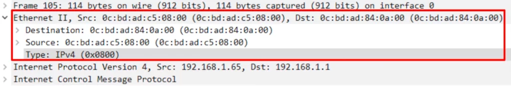
Do you notice the new Ethernet header? The new Ethernet header does not have a dot1q tag. There is no need to tag each frame with dot1q because R1 and SW2 understand that untagged frames belong to VLAN10.
That ICMP echo request will continue to the destination, untagged all the way because VLAN10 is configured as the native VLAN on all devices.
When the PC in VLAN10 sends the ICMP echo reply, it will be untagged until it reaches R1, which will then tag it in VLAN20, and send it back to the PC that sent the ICMP echo request.
>The second method of configuring the native VLAN on a router entails simply configuring the IP address for the native VLAN on the router’s physical interface.
Here is how to configure the native VLAN on R1’s g0/0 interface. First, we use the no interface g0/0.10 command. This deletes the subinterface. Then we enter interface configuration mode for G0/0 and configure the appropriate IP address on the interface.
R1(config)#no interface g0/0.10
R1(config)#interface g0/0
R1(config-if)#ip address 192.168.1.62 255.255.255.192
Here is the output of show running-config for R1’s G0/0 and its subinterfaces.
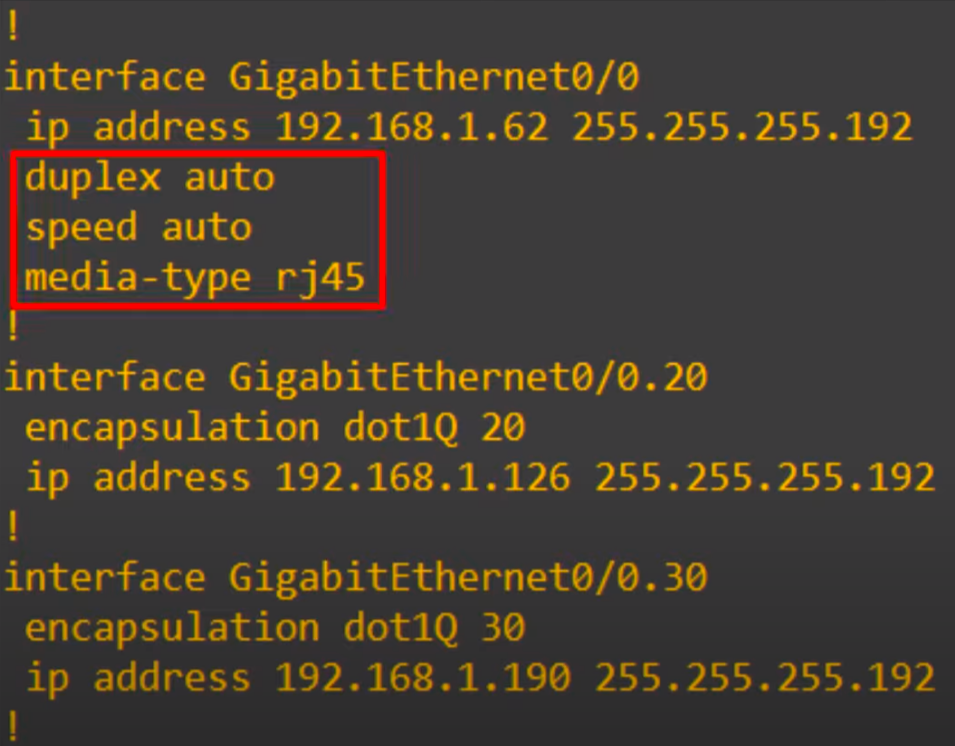
From the top, the physical interface is configured normally with an IP address. This will be used for the native VLAN, VLAN10. Note, the commands in the red box on the router’s physical interface are there by default, we did not configure them.
The other subinterfaces (G0/0.20 and G0/0.30) are just like we configured them in VLANs Part 2, with the encapsulation dot1q command and their own IP address.
This method of configuring the native VLAN on a router will function like the first method. SW2 will send VLAN10 packets in untagged frames to R1, and R1 will also send VLAN10 packets in untagged frames to SW2.
Layer 3 switching/multilayer switching
So far, we have been using L2 switches. Meet the L3 switch, also known as a multilayer switch. On the right hand side are the official Cisco icons for a L2 switch and a L3 switch. Just FYI.
What a multilayer switch does
Regular switches are L2 devices. A regular L2 switch is not L3 aware and does not use IP addresses. However, many modern switches are L3 capable. A multilayer switch is L3 aware.
A multilayer switch is capable of both switching and routing. You can configure routes, such as static routes, on a multilayer switch, just like a router. A L3 switch can be used for inter-VLAN routing.
L3 switches can be configured to route traffic at Layer 3, just like routers. You can assign IP addresses to the switch’s physical interfaces or create virtual interfaces for each VLAN. Virtual interfaces are software-based interfaces that exist in the switch’s firmware. Once you have assigned IP addresses to the switch’s interfaces, you can configure them as routed ports. Routed ports function like physical interfaces on a router, and they can be used to route traffic between different VLANs or to the Internet.
Routing ports are physical interfaces on a switch that can be configured to participate in Layer 3 routing. They can be assigned an IP address and can be used to forward packets between different networks.
Routed ports are logical interfaces on a switch that are created by configuring a Layer 3 switch port as a subinterface. A routed port is associated with a VLAN, and it can be used to forward packets between devices that are connected to the same VLAN. Routed ports are typically used to connect devices within the same VLAN, such as servers or workstations.
Inter-VLAN routing methods – summary
Before looking at the final method of inter-VLAN routing, using SVIs (Switch Virtual Interfaces), let’s do a quick recap of inter-VLAN routing methods.
In these VLANs study notes, we look at three main methods of inter-VLAN routing:
1) Legacy inter-VLAN routing: This is a legacy solution that uses a router with multiple physical interfaces. Each router interface is connected to a switch port configured as an access port in a different VLAN. The router interfaces serve as the default gateways to the local hosts on the VLAN subnet.
We saw this method in VLANs Part 1. There is one connection for each VLAN between the router and switch. A separate physical interface on the router is required for each VLAN. This works, but if you have many VLANs you probably will not have enough interfaces on your router.
2) Router on a stick: This is a more efficient method of inter-VLAN routing that uses a single trunk connection which carries traffic from all VLANs between the switch and router for inter-VLAN routing.
This method is efficient in terms of the number of interfaces, just one, but in a busy network all of the traffic going to the router and back to the switch can cause network congestion.
We look at two variations of this method.
First, using a router interface configured with subinterfaces that function as physical interfaces on a router. Each subinterface is assigned a unique VLAN ID. All traffic received on the physical interface will be tagged with the VLAN ID of the subinterface that it is received on. The router will then route traffic between VLANs based on the VLAN ID of the destination IP address.
In other words, using a single router interface connected to a switch port in trunk mode. The router interface is configured with subinterfaces, each of which is assigned a unique VLAN ID. This allows the router to route traffic between VLANs without having to use multiple physical interfaces.
We covered this method in VLANs Part 2.
Second, using the native VLAN feature on the router. This lesson looks at two variations of this approach. One is using subinterfaces – using the encapsulation dot1q command on the router’s subinterface where a subinterface is configured as a native VLAN which functions just like the native VLAN on a switch. Two is simply configuring the IP address for the native VLAN on the router’s physical interface.
3) Layer 3 switch using switched virtual interfaces (SVIs): This is the most scalable method of inter-VLAN routing. Layer 3 switches have built-in routing capabilities, so they can route traffic between VLANs without the need for a separate router. SVIs are logical interfaces you can assign IP addresses to on a Layer 3 switch. Each SVI is assigned a unique VLAN ID, and it can be used to route traffic to and from that VLAN.
In large networks, a multilayer switch is the preferred method of inter-VLAN routing.
Virtual interfaces are often used in large networks with a large number of VLANs. By creating a virtual interface for each VLAN, you can simplify the routing configuration and make it easier to manage the network.
Virtual interfaces can also be used to provide redundancy. For example, you can create two virtual interfaces for each VLAN and then configure the switch to route traffic over both interfaces. This will help to ensure that traffic is not interrupted if one of the interfaces fails.
Inter-VLAN routing via SVIs (Switch Virtual Interfaces)
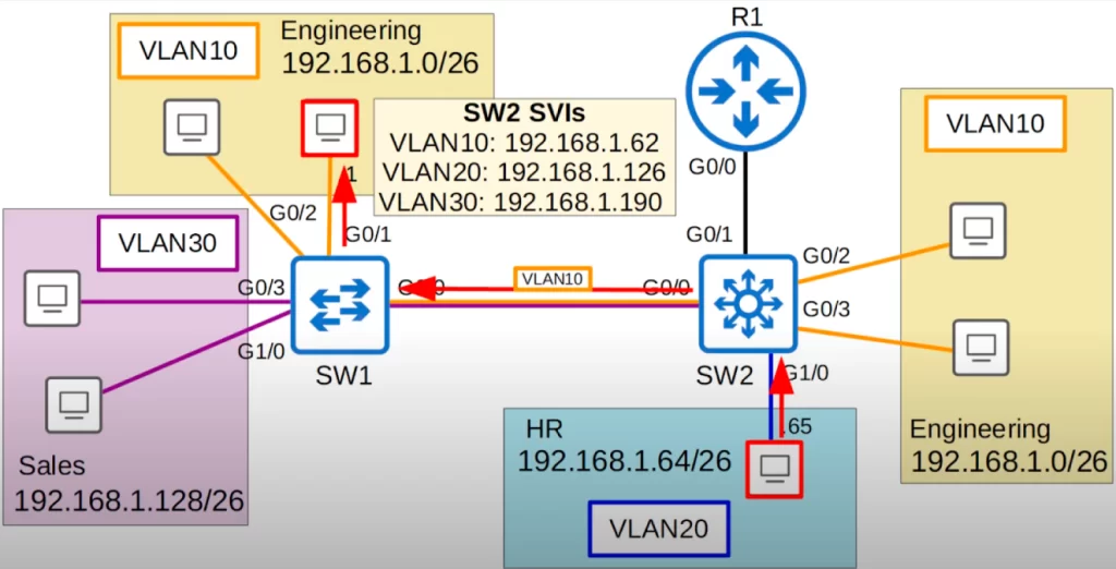
Let’s look at our network diagram again. We replaced SW2 with a multilayer switch. And we replaced the trunk link between SW2 and R1 with a point-to-point L3 link. We will no longer run VLANs across this connection. We will talk about this link later and assign IP addresses to R1’s G0/0 interface and SW2’s G0/1 interface.
For now let’s focus on the inter-VLAN routing done on SW2.
For review, when we used ROAS for inter-VLAN routing (see VLANs Part 2), traffic being routed between VLANs was sent to R1 first and then sent back to SW2, and then forwarded to the destination. For example, if the PC in VLAN20 wants to ping a PC directly connected to SW1 in VLAN10, the traffic would follow a path like this: from the PC to SW2, from SW2 to R1 (tagged in VLAN20), from R1 to SW2 (tagged in VLAN10), from SW2 to SW1 (tagged in VLAN10), and finally to the destination.
However, since SW2 is a multilayer switch, it does not have to send the traffic to R1 for inter-VLAN routing. SW2 can perform inter-VLAN routing using SVIs. Each PC should be configured to use the SVI (not the router) as their gateway address.
When using ROAS, the router was used as the PC’s gateway. This time, we will use the switch’s SVIs instead. To send traffic to different subnets/VLANs, the PCs will send traffic to the switch, and the switch will route the traffic.
SVI configurations
Here three SVIs for three VLANs were configured on SW2. Each SVI was assigned an IP address – the same IP addresses we configured on R1 when doing ROAS, using the last usable IP address in each subnet. These IP addresses are already configured on each PC as their gateway addresses so there is no need to change PC configurations.
We will look at how to configure SVIs on L3 switches for inter-VLAN routing shortly.
Let’s look at the path the traffic between the two PCs takes this time (follow the red arrows). The frame arrives at SW2. The destination is in the 192.168.1.0/26 subnet. SW2 now has its own routing table, so it looks up the destination in the routing table, and sees that the destination is connected to its VLAN10 SVI. So the traffic is now routed to VLAN10. If SW2 does not have the destination MAC address in its MAC address table, it will flood the frame to all VLAN10 interfaces. But let’s assume SW2 has already learned the MAC address, so SW2 forwards the frame to SW1 over its trunk interface, tagged as VLAN10. SW1 then forwards it to the destination.
What if the hosts want to reach destinations outside of the LAN? The cloud connected to R1 represents the Internet. Because SW2 is the default gateway for the hosts, any packets destined outside of the hosts’ subnet will be sent to SW2.
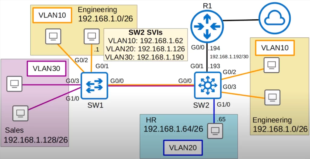
In addition to configuring SVIs on multilayer switches, we can also configure their physical interfaces to operate like a router interface rather than a switchport. So we can assign the subnet 192.168.1.192/30 for this point-to-point link between SW2 and R1, with SW2’s G0/1 interface having an IP address of 192.168.1.193, and R1’s G0/0 interface having an IP address of 192.168.1.194.
Then we configure a default route on SW2 pointing toward R1, so all traffic destined outside of the LAN will be sent to R1.
Let’s configure.
Let’s go over the necessary configurations, starting first with the point-to-point link between SW2 and R1, and then the SVIs on SW2.
First, let’s look at the router’s side of the point-to-point connection.
We start by removing R1’s ROAS configurations and configuring the new IP address on G0/0.
So we deleted each subinterface with the command no interface g0/0.10, .20, and .30. Then we reset G0/0 to its default settings using the command default interface g0/0 because it was configured as a trunk. We then used show ip interface brief to check the interfaces.
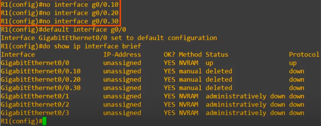
Notice the status of the subinterfaces, it says “deleted.” The deleted status displayed will remain unless we reload the router. Leaving it displayed as deleted is not a problem.
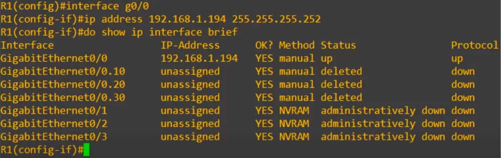
Then we enter interface configuration mode for G0/0 and configure the new IP address with a /30 subnet mask. Using show ip interface brief again, we can see that the new IP address has been successfully configured.
Now let’s look at the switch’s side of the point-to-point connection.
First, we reset SW2’s G0/1 interface to its default setting with the default interface command, because it was configured as a trunk for ROAS previously. Next up is a command you must not forget: ip routing. This command enables L3 routing on the switch. The command lets the switch build its own routing table. If you forget this command, your inter-VLAN routing will not work.
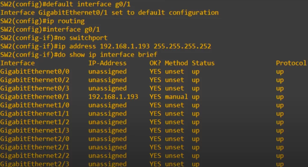
Next up is another important command, no switchport on the interface. This is the command that changes the interface from a L2 switchport to a L3 routed port. Now you will be able to assign an IP address to it. The no switchport command lets you configure an IP address on the switch interface like a regular router interface.
So we assigned 192.168.1.193/30, and used show ip interface brief, and as you can see the IP address is assigned to it just like a router interface.
Lastly is the default route pointing to R1. The command is: ip route 0.0.0.0 0.0.0.0 followed by the next hop, in this case 192.168.1.194, which is R1’s G0/0.
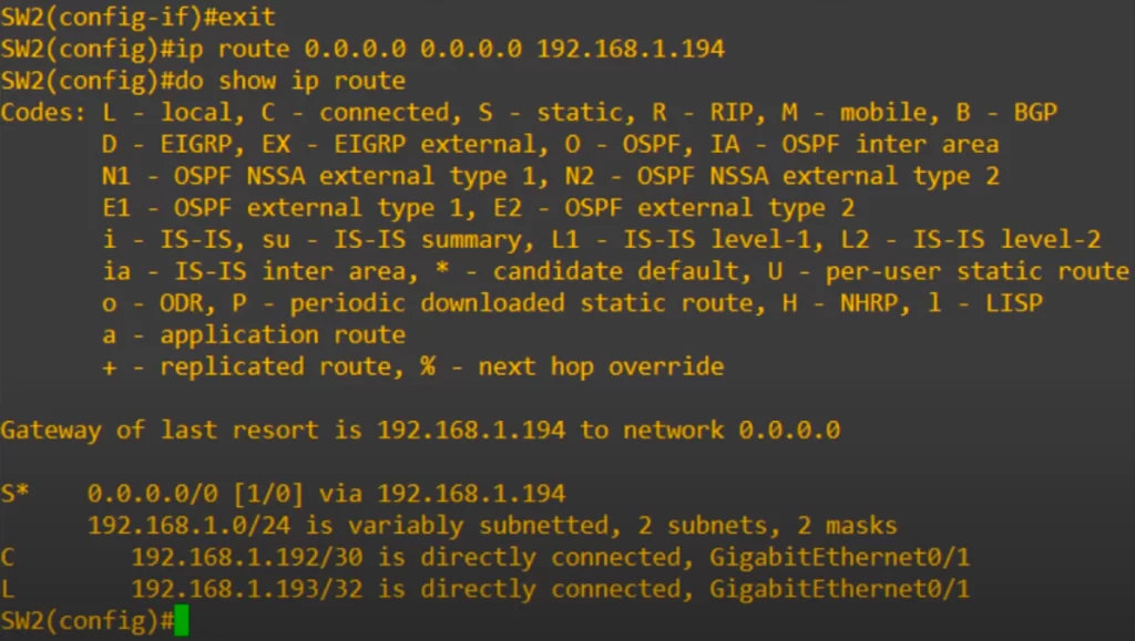
We then use show ip route to confirm, and you can see that SW2 now has a routing table, with a default route pointing to R1 and connected and local routes for the routed interface we configured.
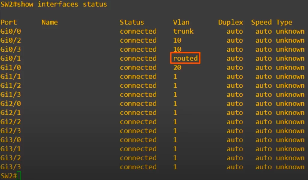
An additional command we can use for confirmation, a command previously discussed in Configuring and verifying switch interfaces, is show interfaces status. Notice that in the VLAN column, instead of a VLAN number, G0/1 displays routed.
Now let’s move on to configure SVIs on SW2.
SVI configuration is simple. Here are the configurations for SW2.
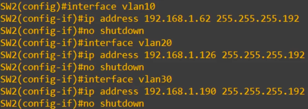
From global config mode, to create a SVI for a VLAN, use the command interface followed by the keyword vlan followed by the vlan number.
For example, to create a SVI for VLAN10 on SW2:
SW2(config)#interface vlan10
Then assign an IP address, and then use no shutdown to enable the SVI. Remember to use the no shutdown command to enable SVIS, because they are shutdown by default.
SW2(config-if)#ip address 192.168.1.62 255.255.255.192
SW2(config-if)#no shutdown
We repeated the process for VLAN20 and VLAN30, and that’s all there is to configuring SVIs.
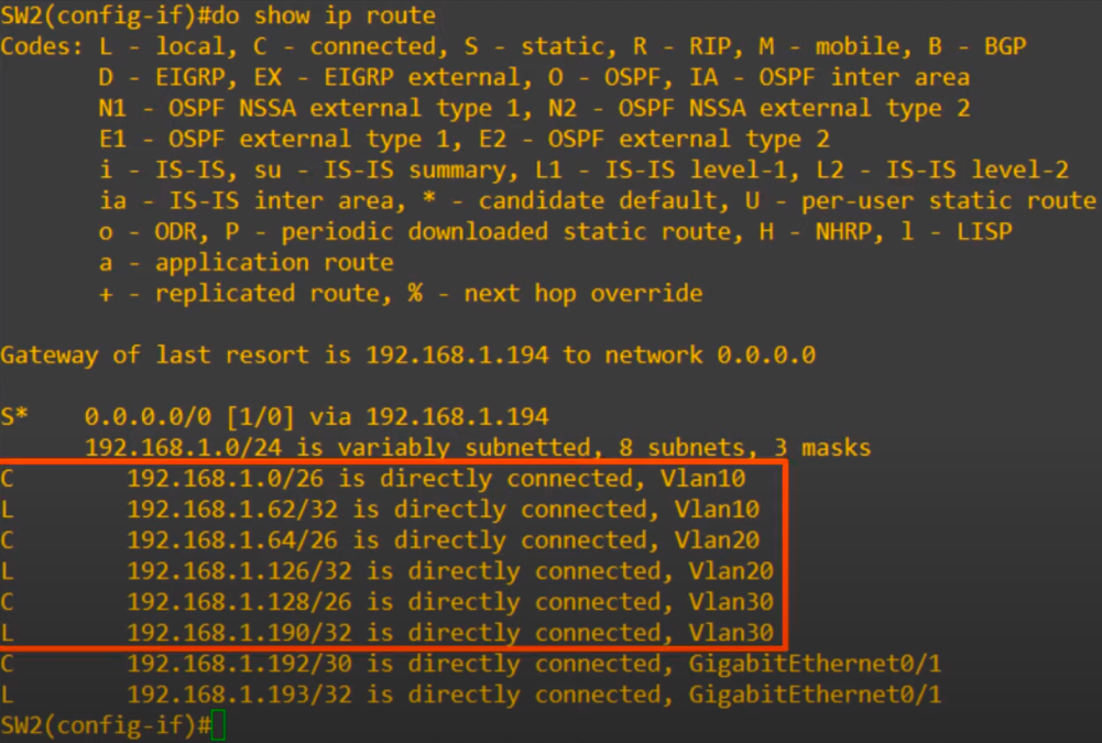
We used the show ip route command again, and you can see connected and local routes have been added to the route table for the SVIs we created, all shown as directly connected to the SVI for each VLAN.
Our configurations are all done.
Note, if one of our PCs wants to reach a destination outside of the LAN, it will be sent to SW2, which will send it to R1, which will take care of it from there. We did not configure any routes on R1, as we are focusing on inter-VLAN routing at this point. If one of our PCs wants to reach a destination in the LAN, but in a different subnet and VLAN, SW2 will do the inter-VLAN routing without having to send the traffic to R1.
Finally for this lesson, let’s go over the conditions required for an SVI to be up/up.
1) The VLAN must exist on the switch.
When you assign an access port to a VLAN, if the VLAN does not yet exist the switch will automatically create the VLAN. However, if you create an SVI for a VLAN that does not yet exist, the switch will not automatically create the VLAN.
What happens if we try to configure an IP address on an SVI for a VLAN that does not exist.
We created a SVI for a VLAN that does not exist on the switch, VLAN40, and assigned an IP address, 40.40.40.40/24. We enabled the interface with no shutdown.
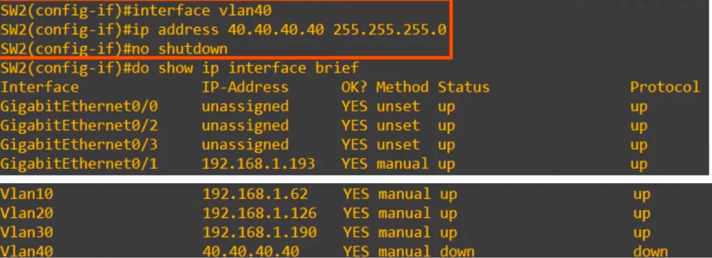
When we check the status of the interface, it is down/down. This is because the VLAN does not exist on the switch.
In this case, we have not created VLAN40 on the switch, so the SVI will not become up/up.
2) The switch must have at least one access port in the VLAN in an up/up state, and/or one trunk port that allows the VLAN that is in an up/up state. For example, in our example network, SW2 has hosts connected in VLAN10 and VLAN20, so their SVIs can go up. SW2 has no connected hosts in VLAN30. However, SW2 has a trunk port, G0/0, which allows VLAN30 over it, so VLAN30’s SVI is up as well.
3) The VLAN must not be shutdown. Note that this is not the SVI, but the VLAN itself. You can enter VLAN configuration mode, and disable the VLAN with the shutdown command. If you do this, the SVI for that VLAN cannot become up/up.
4) The SVI itself is shutdown, so obviously it will not be up/up, so make sure to use the no shutdown command after you create an SVI because SVIs are disabled by default.
Command review
>Configure the native VLAN on a router using the router subinterface (example):
R1(config)#interface g0/0.10
R1(config-subif)#encapsulation dot1q 10 native
>Configure the native VLAN on a router by configuring an IP address on the router’s physical interface (example):
R1(config)#no interface g0/0.10
→to delete the subinterface (if needed)
R1(config)#interface g0/0
R1(config-if)#ip address 192.168.1.62 255.255.255.192
>Configure point-to-point link between SW2 and R1 (example):
Assign the subnet 192.168.1.192/30 for the point-to-point link between SW2 and R1, with SW2’s G0/1 interface having an IP address of 192.168.1.193, and R1’s G0/0 interface having an IP address of 192.168.1.194.
First, the router’s side of the point-to-point connection.
R1(config)#no interface g0/0.10
→to delete the subinterface
R1(config)#default interface g0/0
→to reset G0/0 to its default settings
Then we enter interface configuration mode for R1’s G0/0 and configure the new IP address with a /30 subnet mask.
Next, the switch’s side of the point-to-point connection.
SW2(config)#default interface g0/1
→to reset the interface to default settings (if needed)
SW2(config)#ip routing
→to enable IP routing on a L3 switch
SW2(config)#interface g0/1
SW2(config-if)#no switchport
→to configure the switch interface as a routed port (to change the interface from a L2 switchport to a L3 routed port)
SW2(config-if)#ip address 192.168.1.193 255.255.255.252
>Configure a default route pointing to R1 (example):
SW2(config)#ip route 0.0.0.0 0.0.0.0 192.168.1.194
>SVI configurations on SW2 (example):
SW2(config)#interface vlan10
→to create SVI for VLAN 10
SW2(config-if)#ip address 192.168.1.62 255.255.255.192
SW2(config-if)#no shutdown
Free CCNA | VLANs (Part 3) | Day 18 Lab – Notes
Key learnings
*Two ways of configuring the native VLAN on a router.
*How to read/understand Wireshark captures, both a dot1q-tagged frame, and an untagged frame in the native VLAN.
*How to configure SVIs on a multilayer switch for inter-VLAN routing.
Key references
Note: The resources cited below (in the “Key references” section of this document) are the main source of knowledge for these study notes/this lesson, unless stated otherwise.
Free CCNA | VLANs (Part 3) | Day 18 | CCNA 200-301 Complete Course
Free CCNA | VLANs (Part 3) | Day 18 Lab | CCNA 200-301 Complete Course
Other references/resources
Configure InterVLAN Routing on Layer 3 Switches – Cisco
Inter-VLAN Routing using Layer 3 Switches (4.3) – Cisco Press
Native VLAN on a Router (ROAS). VLANs. Switches. CCNA
Related content
Compliance frameworks and industry standards
Configuring access ports on Cisco switches
Configuring trunk ports on Cisco switches
How data flow through the Internet
How to break into information security
IT career paths – everything you need to know
Job roles in IT and cybersecurity
Network security risk mitigation best practices
The GRC approach to managing cybersecurity
The penetration testing process
The Security Operations Center (SOC) career path
Back to DTI Courses


