In the Ethernet LAN switching lessons we looked at how switches forward frames to their destination. The process routers use to forward packets to their destination is different, and that’s what we start exploring in this lesson. This lesson covers the basics of routing – how routers decide where to forward packets. We look at two types of routes, Connected and Local routes. Those routes are automatically added to the router’s routing table when you configure an IP address on the router’s interface. Connected routes provide a route to a network the router’s interface is directly connected to, and Local routes provide a route to the router’s own IP address.
The next lesson, How to configure static routes on Cisco routers, looks at how to read a routing table, how to configure a static IP address for the eth0 network interface of a PC as the default gateway, and how to configure a default route on a Cisco router.
This lesson first answers the question, what is routing? Then the routing table on a Cisco router is examined. Switches have MAC address tables, and routers have routing tables. It’s very important that you know how to read a router’s routing table. Specifically, we will look at two types of routes found in a routing table: Connected and Local routes. Finally, the lesson looks at routing fundamentals, specifically, route selection. In a router’s routing table, routers will usually have a variety of routes. We will discuss how the router selects the correct route for a packet. This post constitutes Issue 8 of my CCNA 200-301 study notes.
- What is routing?
- R1 pre-configurations (IP addresses)
- Routing table (show ip route)
- Connected and Local routes
- Route selection
- Route selection practice (1)
- Route selection practice (2)
- Route selection practice (3)
- Route selection practice (4)
- Route selection practice (5)
- Summary
- Command review
- Key learnings
- Practice quiz questions
- Key references
You may also be interested in CCNA 200-301 study notes.
What is routing?
*Routing is the process that routers use to determine the path that IP packets should take over a network to reach their destination. When a router receives a packet, it’s the router’s job to forward the packet to the correct destination.
Routers store routes to all of their known destinations in a routing table. When routers receive packets, they look in the routing table to find the best route to forward that packet.
*A route is an instruction to the router. A route tells the router: to send a packet to destination X, you should send the packet to next-hop Y. Next hop means the next router in the path to the destination.
Or, if the destination is directly connected to the router, send the packet directly to the destination. Or, if the destination is the router’s own IP address, receive the packet for yourself, do not forward it.
*There are two main routing methods (methods routers use to learn routes):
- Dynamic routing, in which routers use dynamic routing protocols such as OSPF to share routing information with each other automatically and build their routing tables.
- Static routing. In this case, a network engineer or network admin manually configures routes on the router.
This lesson covers Connected and Local routes, both do not fit into either of the above two categories.
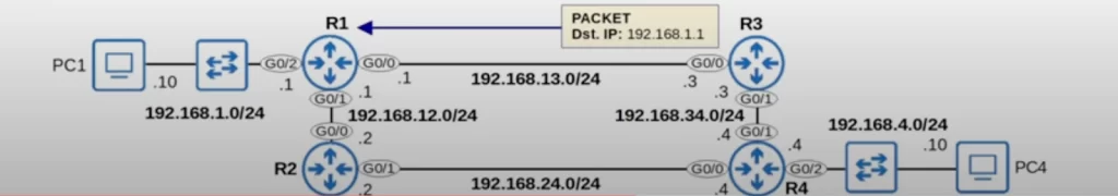
To demonstrate routing concepts we will use the following example network.
There are four routers connected together, and they represent a Wide Area Network. A WAN is a network that extends over a large geographical area. For example, each of these four routers could be in different cities or even different countries. Connected to R1 and R4 are two LANs. Each of these LANs can be a different office in a different city, and each could be connected to many more hosts than is shown here. R2 and R3 each can have their own connected LANs too.
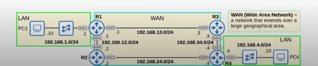
Now let’s look at the IP addresses each device will be using.
>For the LAN connected to R1, the network is 192.168.1.0/24 and R1’s G0/2 interface IP is 192.168.1.1 and PC1’s IP is 192.168.1.10.
>The WAN connection between R1 and R2 is 192.168.12.0/24. R1 G0/1’s IP is 192.168.12.1 and R2 G0/0’s IP is 192.168.12.2.
>The WAN connection between R1 and R3 is 192.168.13.0/24, with R1 G0/0 as 192.168.13.1 and R3 G0/0 as 192.168.13.3.
>The WAN connection between R2 and R4 is 192.168.24.0/24, with R2 G0/1 as 192.168.24.2 and R4 G0/0 as 192.168.24.4.
>The final WAN connection between R3 and R4 is 192.168.34.0/24, with R3 G0/1 as 192.168.34.3 and R4 G0/1 as 192.168.34.4.
>Then, the LAN connected to R4’s G0/2 interface is 192.168.4.0/24, with R4 G0/2 as 192.168.4.4 and PC4 as 192.168.4.10.
Notice that all the router IP addresses are the same as their name. All of R1’s IP addresses are .1, R2’s IP addresses are .2, R3’s are .3, etc.
R1 pre-configurations (IP addresses)
Before looking at routes, let’s configure the IP addresses using the Cisco IOS CLI. Only the configurations on R1 are shown (see the following diagram) since that’s the router we’ll be focusing on in this lesson.
From the top, from privileged EXEC mode, we enter “conf t” (configure terminal) to enter global configuration mode. We then enter interface configuration mode by typing the keyword interface followed by the interface name.
First we configured R1’s G0/0 interface with ip address 192.168.13.1 255.255.255.0, and then enabled it with no shutdown.
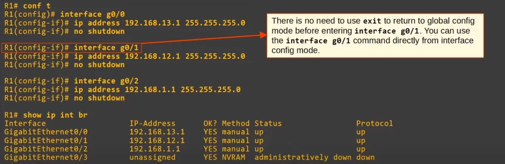
Then we configured G0/1’s IP address. We can use the INTERFACE G0/1 command directly from G0/0 interface config mode, without returning to global config mode first.
We then configured G0/2.
To confirm, we used SHOW IP INTERFACE BRIEF, and you can see the IP addresses we just configured. The other routers’ IP addresses were configured too, though not shown here.
Routing table (show ip route)
Let’s look at R1’s routing table. The command SHOW IP ROUTE displays the router’s routing table. Here is the output. There are two main sections to the output, the “Codes” at the top, and the actual routes at the bottom.
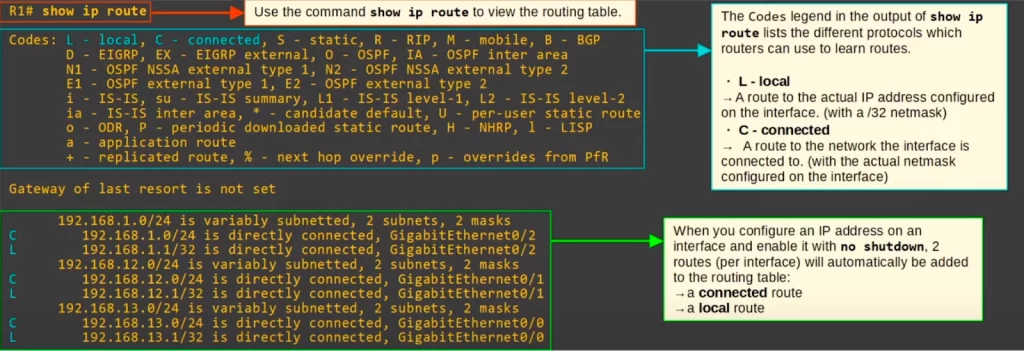
The Codes legend in the output of SHOW IP ROUTE lists the different protocols which routers can use to learn routes, as well as the codes that represent the protocols in the routing table. Note the two codes highlighted in blue in the diagram. L, Local, and C, Connected.
The code L is used for routes to the actual IP address configured on the router’s interface, and these routes will have a /32 mask. If you look at the routes below in the above diagram, notice there are three routes with L highlighted in blue, one for each of R1’s interfaces. The code C is used for routes to the network the interface is connected to, with the actual netmask (subnet mask) configured on the interface. Notice there are also three routes with the C code in the output.
Even though we haven’t configured any routes yet on R1, R1 already has six routes. When you configure an IP address on an interface and enable it with the NO SHUTDOWN command, two routes per interface will be automatically added to the routing table, a connected route, and a local route.
Note, the statement “192.168.1.0/24 is variably subnetted, 2 subnets, 2 masks” means that in the routing table there are two routes to subnets that fit within the 192.168.1.0/24 Class C network, with two different subnet masks, those being /24 and /32. The other two similarly-worded lines mean the same thing for their respective networks.
Connected and Local routes
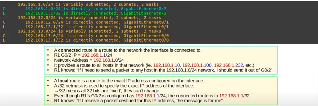
In the following CLI output, two routes are highlighted for R1’s G0/2 interface: one connected route to 192.168.1.0/24 and one local route to 192.168.1.1/32.
First, let’s look at the connected route in more detail.
*A connected route is a route to the network the interface is connected to.
*R1 G0/2’s IP is 192.168.1.1/24. Because it’s a /24 address the first 24 bits, the first 3 octets, are the network portion of the address. The network portion is highlighted in red. The last octet is the host portion of the address, highlighted in blue.
*When you change that host portion to all 0s, the result is 192.168.1.0/24, and notice that’s the destination of that connected route. It’s a route to that network. So, this provides a route to all hosts in that network, for example 192.168.1.10, .100, .232, etc., any address in that .0/24 range.
*Look back at the routing table, and notice that the connected route says “192.168.1.0/24 is directly connected, GigabitEthernet0/2”. So, R1 knows if it needs to send a packet to any host in that network, it should send it out of G0/2.
Next, let’s look at the local route.
*A local route is a route to the exact IP address configured on the interface.
*A /32 netmask is used to specify the exact IP address of the interface. /32 means that all 32 bits are fixed, they cannot change.
*Even though R1’s G0/2 is configured as 192.168.1.1/24, the local route is to .1/32, which specifies only that single address. With this route R1 knows: if I receive a packet for this IP address, it’s for me.
/24 means that the netmask is 255.255.255.0. The first 24 bits of the netmask are all 1, so each octet is 255. These bits are fixed. However the last 8 bits are not fixed. They can be any number. So the route for 192.168.1.0/24 matches 192.168.1.0 to 192.168.1.255. That means that if R1 receives a packet with a destination in that range, it will send the packet out of the G0/2 interface.
A route matches a packet’s destination if the packet’s destination IP address is part of the network specified in the route.
Examples:
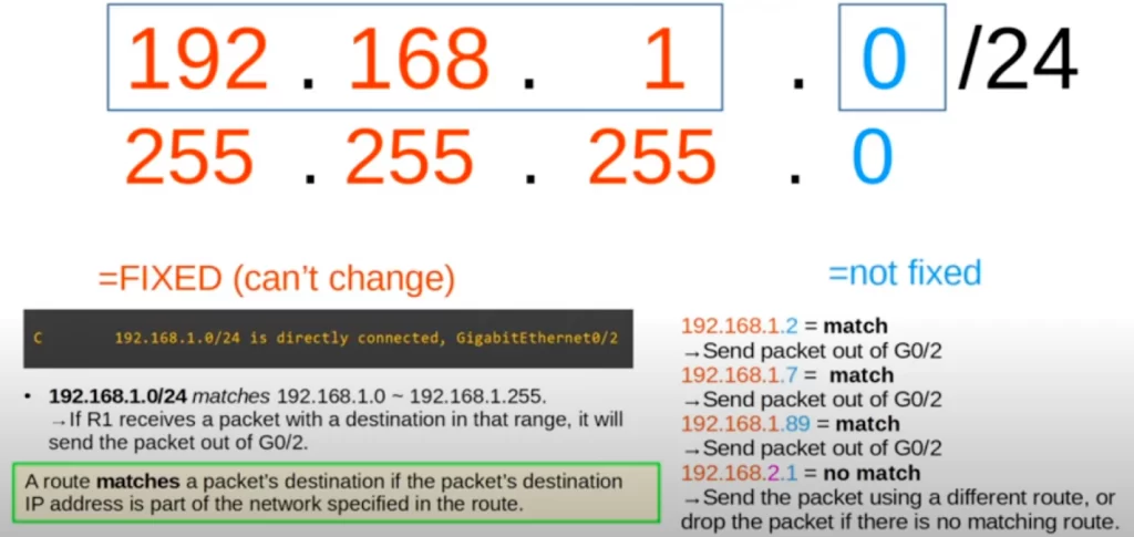
A packet with a destination IP address of 192.168.1.2 is a match in the 192.168.1.0/24 network because 192.168.1.2 begins with 192.168.1. Because it’s /24, the first 3 octets have to match. So, R1 would send the packet out of G0/2. 192.168.1.7 would also match this route, so R1 would forward the packet out of G0/2. Ditto for 192.168.1.89.
A packet destined for 192.168.2.1, however, does not match. R1 cannot use this route, because the destination does not begin with 192.168.1. So R1 would either send the packet using a different route or drop the packet if there is no matching route.
The local route to 192.168.1.1/32 is simpler. Because it’s /32, all bits of the netmask are 1, so it’s 255.255.255.255. All the bits of the IP address are fixed. 192.168.1.1/32 matches only destination 192.168.1.1.
Route selection
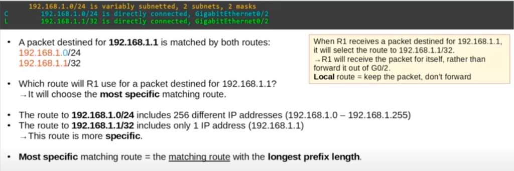
R1 has a connected route to 192.168.1.0/24 and a local route to 192.168.1.1/32. Let’s say R1 receives a packet with a destination IP 192.168.1.1. Can you see the problem here? A packet destined for 192.168.1.1 is matched by both routes 192.168.1.0/24 and 192.168.1.1/32.
So which route will R1 use for a packet destined for 1.1? Will R1 send the packet out of G0/2, or will it receive the packet, because the packet is for R1 itself? R1 will choose the most specific matching route, i.e., the matching route with the longest prefix length.
The route to 192.168.1.0/24 includes 256 different IP addresses, from 192.168.1.0 to .255. On the other hand, the route to 1.1/32 includes only one IP address, 192.168.1.1. The .1/32 route is more specific than the .0/24 route. So when R1 receives a packet destined for 192.168.1.1, it will select the route to 1.1/32, i.e., R1 will receive the packet for itself, rather than forward it out of G0/2.
Local routes tell the router: keep the packet, don’t forward it. This means R1 will de-encapsulate the packet and look at the contents inside, because the contents are addressed to R1 itself.
To summarize: the route that the router will use for the packet is the most specific matching route, the matching route with the longest prefix length. The route must match the packet’s destination and it also must have the longest prefix length out of all of the matching routes.
Route selection practice (1)
Let’s look at a few examples to practice route selection.
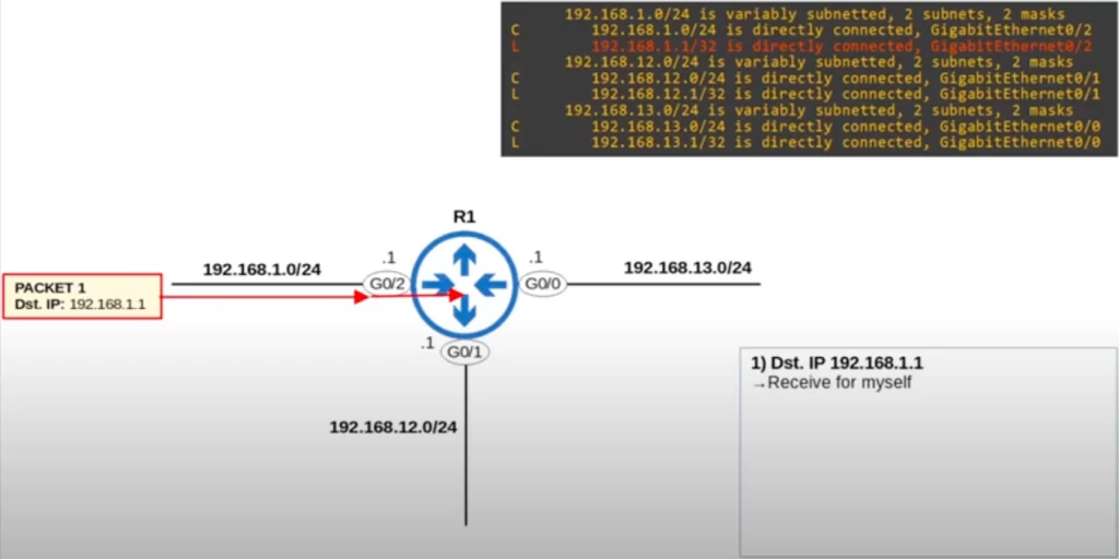
R1 receives a packet destined for 192.168.1.1. Looking at R1’s routing table, which route will R1 select for this packet? And what will it do with the packet?
We have to find the most specific matching route in the routing table. This packet is destined for 192.168.1.1, and when R1 checks its routing table it will see that the most specific match is to 192.168.1.1/32 (highlighted in red). It is a local route, so R1 will receive the packet for itself.
Route selection practice (2)
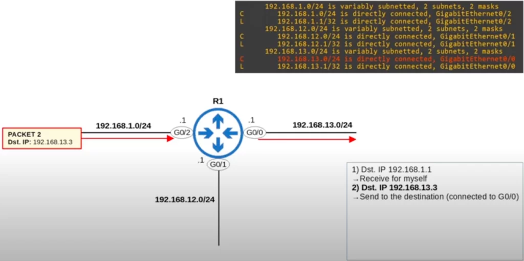
Packet 2 has a destination IP address of 192.168.13.3. Which route will R1 select for this packet? And what will it do with the packet?
The most specific matching route, actually the only matching route for this packet, is this connected route to 13.0/24. So, R1 will send the packet to the destination, which is connected to the G0/0 interface.
Route selection practice (3)
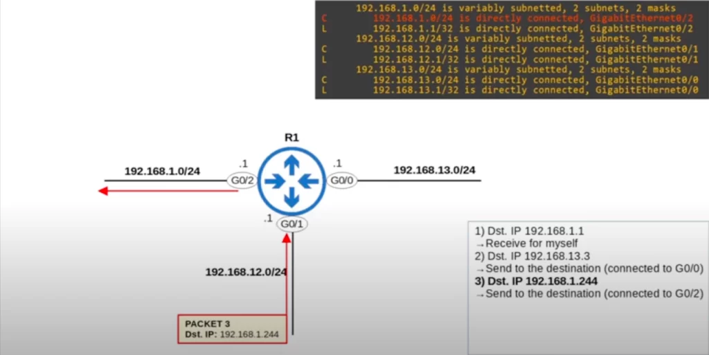
This packet has the destination IP 192.168.1.244. What will R1 do with this packet?
The only matching route is this one to 1.0/24, so R1 will use this route to forward the packet. It’s a connected route, so R1 will send the packet to the destination, which should be connected to that interface.
Route selection practice (4)
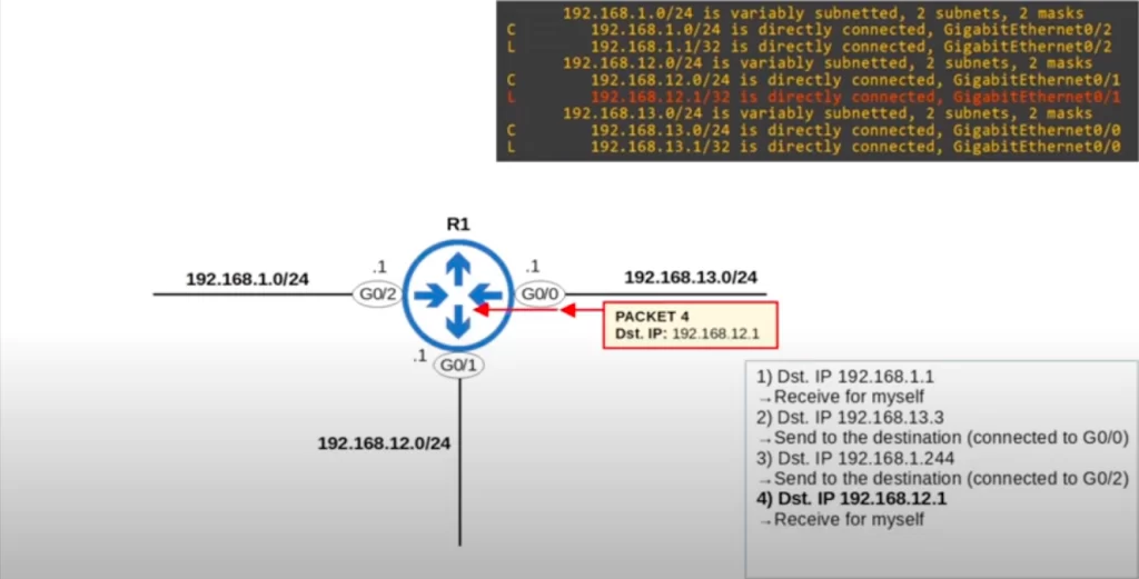
This packet is destined for 192.168.12.1. What will R1 do with this packet?
There are two matching routes, but the most specific one is this Local route for 192.168.12.1/32. So R1 will receive the packet for itself.
Route selection practice (5)
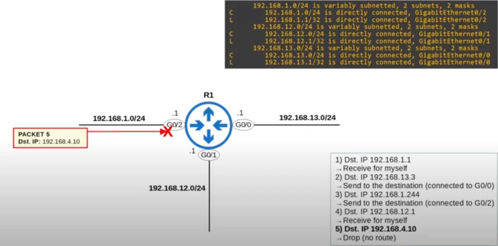
This packet is destined for 192.168.4.10. What will R1 do with this one?
Because there are no matching routes in the routing table, R1 will have to drop this packet. If the router does not have a route to the packet’s destination, it will drop the packet.
Summary
*Routers store information about destinations they know in their routing table.
When routers receive packets, they look in the routing table to find the best route to forward the packet.
*Each route in the routing table is an instruction. The routing table is a set of instructions for the router, telling it how to forward packets.
A route tells the router, to reach destinations in network X, send the packet to next-hop Y, which is the next router in the path to the destination. To reach destination X, send packets to next-hop Y. This lesson focused on connected and local routes.
A route tells the router, if the destination is directly connected (Connected route) to this router, send the packet directly to the destination. Or, if the destination is your own IP address (Local route), receive the packet for yourself.
*When you configure an IP address on an interface and enable the interface, two routes are automatically added to the routing table.
>The first is a Connected route, indicated with code C in the routing table. It is a route to the network connected to the interface.
–For example, if the interface’s IP is 192.168.1.1/24, the connected route will be to 1.0/24.
–It tells the router: to send a packet to a destination in this network, send it out of the interface specified in the route.
>The second kind of route is a Local route, indicated by code L in the routing table. It’s a route to the exact IP address configured on the interface.
–So, if the interface’s IP is 192.168.1.1/24, the local route will be to 1.1/32. A /32 netmask is used to specify just the one IP address.
–This tells the router, packets to this destination are for you, and you should receive them for yourself and not forward them.
*Routes match destinations. A route matches a destination if the packet’s destination IP address is part of the network specified in the route.
–For example, a packet to 192.168.1.60 is matched by a route to 192.168.1.0/24, but not by a route to 192.168.0.0/24.
*If a router receives a packet and it does not have a route that matches the packet’s destination, it will drop the packet.
–This is different from switches, which flood frames if they don’t have a MAC table entry for the destination.
*If a router receives a packet and it has multiple routes that match the packet’s destination, it will use the most specific matching route to forward the packet.
–The most specific matching route means the matching route with the longest prefix length.
–This is different from switches, which look for an exact match in the MAC address table to forward frames. The frame’s destination MAC address must be the exact same as the entry in the MAC address table. There’s no concept of “most specific match” in switches.
Command review
*Router pre-configurations (configure an IP address on a router interface):
R(config)#interface interface-name
R(config-if)#ip address ip-address subnet-mask
R(config-if)#description description
R(config-if)#no shutdown
R#show ip interface [interface-type interface-number] [brief]
R#show ip route
Key learnings
*What is routing?
*How to read the routing table on a Cisco router, specifically looking at Connected and Local routes.
*Routing fundamentals (route selection) – how routers select which route to use to forward a particular packet.
Practice quiz questions
Quiz question 1
The IP address configured on a router interface will appear in the routing table as what kind of route?
a) Static
b) Connected
c) Local
d) Dynamic
The answer is C, local. When you configure an IP address on an interface, two routes are automatically added to the router’s routing table, assuming the interface is enabled, a connected route to the network, and a local route to the exact IP address configured on the router interface.
You can find four more practice questions for this lesson in Jeremy’s video lesson Routing Fundamentals (part 1), cited below.
Key references
Note: The resources cited below (in the “Key references” section of this document) are the main source of knowledge for these study notes/this lesson, unless stated otherwise.
Free CCNA | Routing Fundamentals | Day 11 (part 1) | CCNA 200-301 Complete Course
Related content
Compliance frameworks and industry standards
How data flow through the Internet
How to break into information security
IT career paths – everything you need to know
Job roles in IT and cybersecurity
Network security risk mitigation best practices
The GRC approach to managing cybersecurity
The penetration testing process
The Security Operations Center (SOC) career path
Back to DTI Courses


