In this lesson we learn how to configure static routes in the CLI of Cisco routers. Static routing is a very important topic in computer networking and for the CCNA. In the previous lesson, Connected and local routes, we looked at the basics of routing, how routers decide where to forward packets. We explored two types of routes – Connected and Local routes.
Connected routes provide a route to a network the router’s interface is directly connected to, and Local routes provide a route to the router’s own IP address. However, for the router to be able to send traffic to destinations not directly connected to the router itself, Connected and Local routes are not enough. Static routes enable routers to send packets to remote destinations not directly connected to the router itself. Unlike Connected and Local routes, static routes are not automatically added to the routing table and must be manually configured.
First we review Connected and Local routes. Next is an introduction to static routes and an explanation of how we can use static routes to instruct routers about how to forward packets. Then we will look at how to configure static routes in the CLI of Cisco routers. Finally, default routes are explained and we look at how to configure a default route on a Cisco router. This post constitutes Issue 9 of my CCNA 200-301 study notes.
- Connected and Local routes – review
- Default gateway – routing packets
- Routing packets between end hosts in different networks (PC1 and PC4)
- Static routes: planning
- Static routes: configuration
- PC1 to PC4 communication
- Static route configuration (exit interface)
- Default route
- Command review
- Key learnings
- Practice quiz questions
- Key references
You may also be interested in CCNA 200-301 study notes.
Connected and Local routes – review
Let’s first review Connected and Local routes by configuring IP addresses on the routers and checking their routing tables.
In the last lesson, Connected and local routes, we configured R1, so this time let’s start from R2.
Here are R2’s configurations. We configured IP addresses on R2’s G0/0 and G0/1 interfaces and enabled both interfaces with no shutdown.
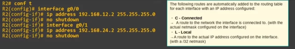
Recall, when you configure IP addresses on router interfaces, connected and local routes are added automatically in the routing table. One connected route and one local route per interface are added. So we can expect to find four routes already added in R2’s routing table. Remember, if an interface is disabled the connected and local routes for that interface will not appear in the routing table.
The connected routes are routes to the networks which R2’s interfaces are connected to. So there should be one route to 192.168.12.0/24 and one route to 192.168.24.0/24. And then the local routes are to the exact IP addresses configured on R2’s interfaces, so there should be a route to 192.168.12.2/32 and a route to 192.168.24.2/32.
Here are the routes.
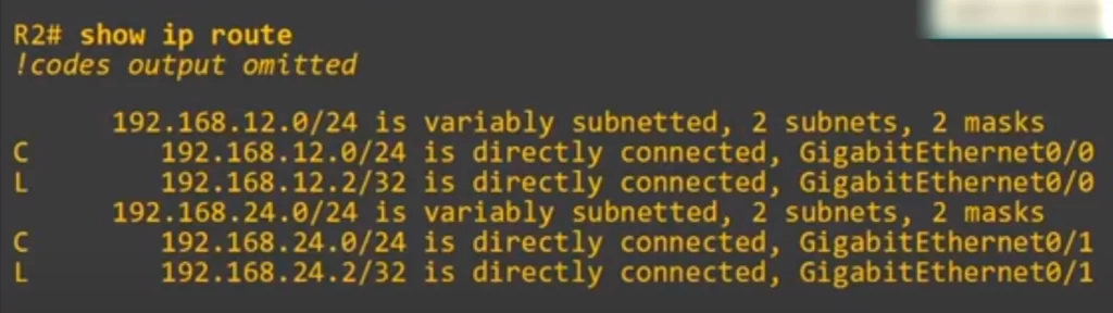
As expected, R2 has two connected routes: one to 12.0/24 and one to 24.0/24. R2 also has two local routes, one to 12.2/32 and one to 24.2/32.
To summarize: R2 knows how to reach its own IP addresses and destinations in its connected networks, but it does not know how to reach destinations in remote networks (networks not directly connected to R2). So R2 knows how to reach destinations in the 192.168.12.0/24 and 192.168.24.0/24 networks, including its own IP addresses in those networks. But it does not know how to reach any of the other networks in the network topology. If R2 receives packets destined for hosts in these other networks, it will have to drop them.
And here are R3’s configurations. 192.168.13.3/24 on its G0/0 interface and 192.168.34.3/24 on G0/1.
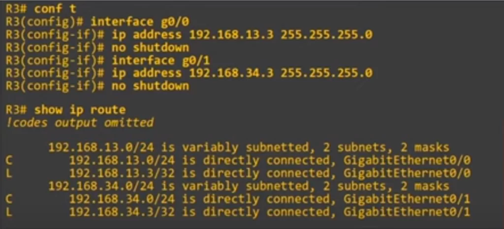
R3’s routing table shows R3 has two Connected and two Local routes. Like on R2, R3 knows how to reach destinations in its connected networks, those are the connected routes, and its own IP addresses, those are the local routes. So R3 knows how to reach 192.168.13.0/24, including its own IP of 13.3/32, and it also knows how to reach 34.0/24, including its own IP of 34.3/32. But R3 does not know how to reach any of the other networks. So, for example, if R3 receives a packet and the destination is PC4’s IP address, 192.168.4.10, R3 would have to drop the packet.
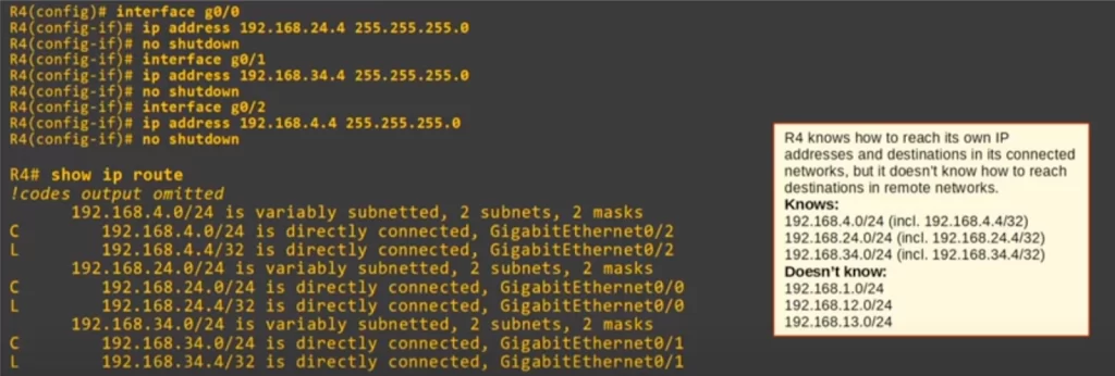
And here are R4’s configurations. R4 has three interfaces in use, so it will have six routes in its routing table, three Connected and three Local.
Now let’s start looking at how to configure the routers to allow PC1 and PC4 to communicate. So we are going to start looking at how packets move through the network. First, we are going to look at the concept of default gateway.
Default gateway – routing packets
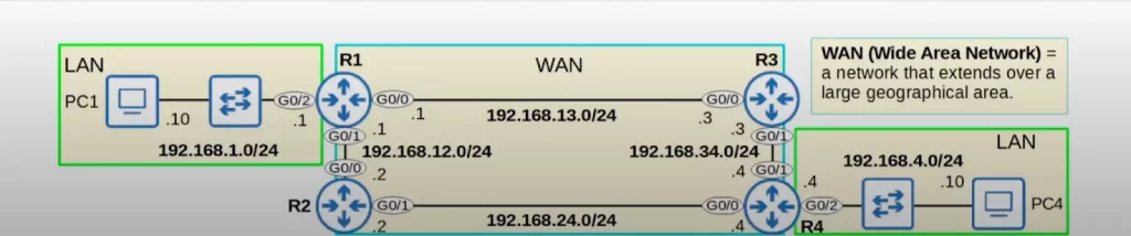
Here is our network topology, in a new, colorful dress.
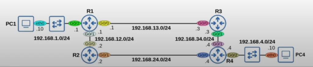
The interface labels for each device have been colored, and PC1 and PC4 are given interface names. PC1 and PC4 are Linux hosts, and their default interface name is eth0, Ethernet0.
*End hosts like PC1 and PC4 can send packets directly to destinations in their connected network. PC1 is connected to 192.168.1.0/24, so it can directly communicate with other hosts in that network, and PC4 is connected to 192.168.4.0/24, so it can directly communicate with hosts in that network.
*However, to send packets to destinations outside of their local network, PC1 and PC4 must send the packets to their default gateway, i.e., their default router.
The default gateway is the router that is responsible for routing packets to networks that are not on the local subnet.
Here are the configurations on PC1 and PC4. In Linux, the interface configurations are stored in a text file that you can edit.
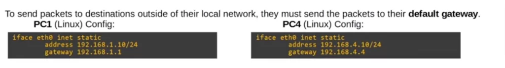
On PC1, e.g., the line “address 192.168.1.10/24” configures PC1’s IP address as 192.168.1.10 with a prefix length of /24. And below that is the default gateway configuration, “gateway 192.168.1.1”. So to send packets to destinations outside of its local network, PC1 will send packets to R1.
The iface eth0 inet static line in Linux is used to configure a static IP address for the eth0 network interface. The iface keyword tells the kernel that this is a network interface configuration, the eth0 is the name of the network interface, the inet keyword tells the kernel that this is a static IP address, and the static keyword tells the kernel that the IP address is not going to be dynamically assigned by a DHCP server.
The rest of the line would typically specify the IP address, subnet mask, gateway, and DNS servers for the eth0 network interface. For example, the following line would configure the eth0 network interface with an IP address of 192.168.1.10, a subnet mask of 255.255.255.0, a gateway of 192.168.1.1, and DNS servers of 192.168.1.1 and 8.8.8.8:
iface eth0 inet static
address 192.168.1.10
netmask 255.255.255.0
gateway 192.168.1.1
dns-nameservers 192.168.1.1 8.8.8.8
To configure a static IP address for the eth0 network interface, you would need to edit the /etc/network/interfaces file and add the iface eth0 inet static line. You would also need to restart the networking service for the changes to take effect.
*End hosts usually have no need for any more specific routes. End hosts just need to know: to send packets outside of my local network, I should send them to my default gateway.
If PC1 wants to send a packet to PC4, the source IP address in the IP header is PC1’s IP, 192.168.1.10. And the destination IP is PC4’s IP, 192.168.4.10. But what will the source and destination MAC addresses be in the Ethernet header? The source MAC address will be PC1’s MAC address. The destination will be the next hop router’s MAC address, R1’s MAC address. PC1 has to first forward the packet to its default gateway, R1. So PC1 will encapsulate the packet in a frame and the destination MAC will be R1 G0/2’s MAC address. For PC1 to learn R1 G0/2’s MAC address, PC1 will need to send an ARP request to 192.168.1.1, R1 G0/2’s IP address.
Jeremy McDowell’s YouTube lesson “The Life of a Packet” covers this process in more detail: Free CCNA | The Life of a Packet | Day 12 | CCNA 200-301 Complete Course
To keep things simple in this lesson, we will assume that each device already knows its neighbor’s MAC address.
Routing packets between end hosts in different networks (PC1 and PC4)
PC1 wants to send a packet to PC4. The source IP address is 192.168.1.10, PC1’s IP. And the destination IP is 192.168.4.10, PC4’s IP. So PC1 sends that packet to its default gateway, R1.
*When R1 receives the frame on its 192.168.1.1 G0/2 interface, R1 will de-encapsulate the frame, meaning it will remove the Layer 2 header and trailer, and look at the inside packet.
*R1 will then check the routing table for the most-specific matching route. R1 has to make a decision about what it will do with this packet. Here is R1’s routing table at the moment, just Connected and Local routes.
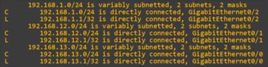
*R1 has no matching routes in its routing table. R1 has no choice but to drop the packet. As it stands, R1 does not know how to forward the packet.
*To forward the packet, R1 needs a route to the destination network, 192.168.4.0/24. R1 needs a route to say: to send a packet to destinations in network 192.168.4.0/24, forward the packet to next hop Y.
What should be the next hop? What is the next router in the path to the destination?
*Packets from PC1 to PC4 can follow two paths.
Path 1 via R3. PC1 to R1 to R3 to R4 to PC4.
Path 2 via R2. PC1 to R1 to R2 to R4 to PC4.
In this lesson we will use path 1, the path via R3.
It is possible to configure the routers to use both paths. Instead of choosing one path, they can load-balance between path 1 and 2. That means some packets will take path 1 and some will take path 2. Or they could, for example, use path 1 as the main path and path 2 as a backup path. These techniques are discussed in future lessons.
Static routes: planning
*For PC1 and PC4 to communicate with each other, every router in the path needs two routes: a route to 192.168.1.0/24, PC1’s network, and a route to 192.168.4.0/24, PC4’s network. This ensures two-way reachability, which means that PC1 can send packets to PC4, and PC4 can send packets to PC1.
*R1 already has a connected route to 192.168.1.0/24, and R4 already has a connected route to 192.168.4.0/24. However, the other routes must be manually configured, using static routes.
Routers do not need routes to all networks in the path to the destination. For example, R1 does not need a route to 192.168.34.0/24. R1 just needs to know: to send packets to 192.168.4.0/24, I should send the packets to R3. R3 will take care of the packets after that. Likewise, R4 does not need a route to 192.168.13.0/24. R4 just needs to know: to send packets to 192.168.1.0/24, I should send the packets to R3. R3 will take care of the packets after that.
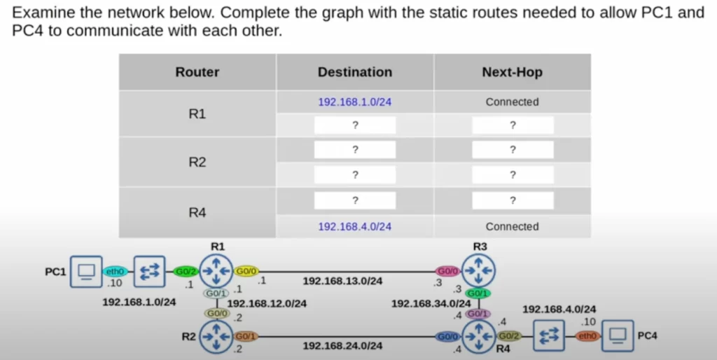
Before we get into configuring static routes, let’s plan out the routes we will configure. Here is a chart of the routes R1, R3, and R4 need to allow PC1 and PC4 to communicate with each other.
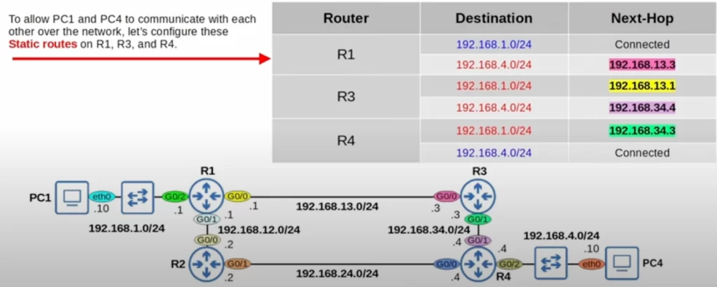
In the destination column, in blue are R1’s and R4’s connected routes – the next hop is listed as connected. In the destination column, in red are the static routes we have to configure. Remember, we are using path 1 via R3, i.e., PC1 to R1 to R3 to R4 to PC4.
For R1 to send a packet to the 4.0/24 network, the next-hop IP address is 192.168.13.3, the IP address of R3’s G0/0 interface. R1 has a connected route to 192.168.13.0/24, so it knows how to reach 13.3. R1 can use that IP address as a next-hop to send packets toward the 4.0/24 network.
R3 should use 192.168.13.1, R1’s G0/0 interface, as the next hop IP to send packets to the 192.168.1.0/24 network. R3 should use 192.168.34.4, R4’s G0/1 interface, to send packets to the 4.0/24 network.
R4 should use 192.168.34.3, the IP address of R3’s G0/1 interface, to send packets to the 1.0/24 network.
Now that we’ve planned the static routes we need to configure to allow PC1 and PC4 to communicate with each other over the network, let’s go ahead and configure these static routes on R1, R3, and R4.
Static routes: configuration
Here is the format of the command. From global config mode, IP ROUTE, followed by the destination network IP, netmask, and next-hop IP.
R4(config)#ip route ip-address netmask next-hop
*Static route configuration (R1)
First, let’s configure R1’s route to 192.168.4.0/24.
For R1’s route to the 4.0/24 network The command is IP ROUTE 192.168.4.0 255.255.255.0 192.168.13.3. Next, we check R1’s routing table.
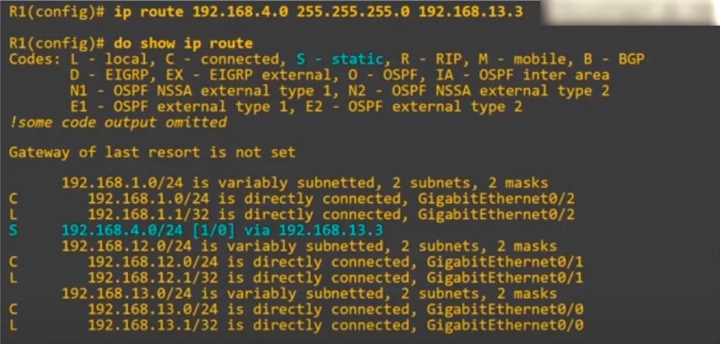
The code for static routes is highlighted in blue, it’s S. The route is also highlighted in the table. Notice in square brackets there are two numbers: 1/0. These numbers are the route’s administrative distance and metric.
That’s all we have to configure on R1. R1 now knows that to reach PC4’s network, it should forward packets to 192.168.13.3, R3.
*Static route configuration (R3)
R3 needs two routes, one to 1.0/24 and one to 4.0/24. The format of the commands on R3 is the same as on R1. Here is the route to the 192.168.1.0/24 network with R1 as the next hop, and the route to 192.168.4.0/24 with R4 as the next hop.
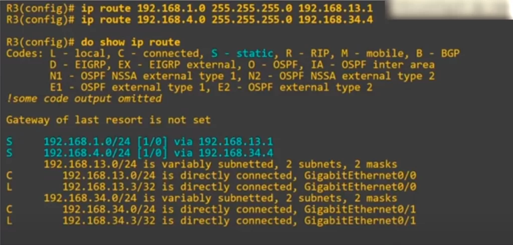
When we check R3’s routing table, we can see both routes there with their next-hop IP addresses. To reach 192.168.1.0/24, send packets to R1. To reach 4.0/24, send packets to R4. All is hunky-dory.
*Static route configuration (R4)
Finally, let’s configure R4’s route to the 192.168.1.0/24 network, thus: IP ROUTE 192.168.1.0 255.255.255.0 192.168.34.3, using R3’s G0/1 interface IP address as the next hop. Here’s R4’s routing table.
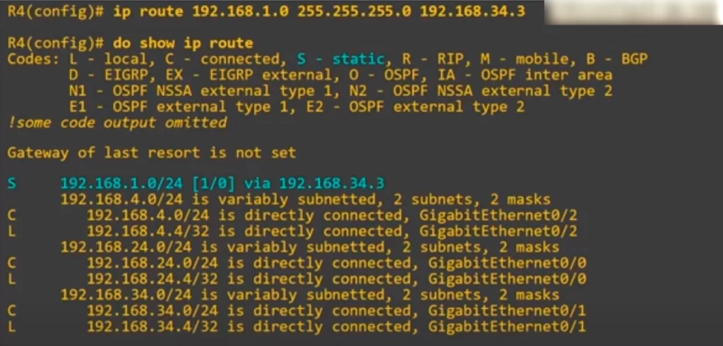
We have now configured all of the static routes necessary for PC1 and PC4 to communicate. Let’s test the configurations.
PC1 to PC4 communication
To test the configurations, we ping from PC1 to PC4. The ping is successful, so the configurations were successful.
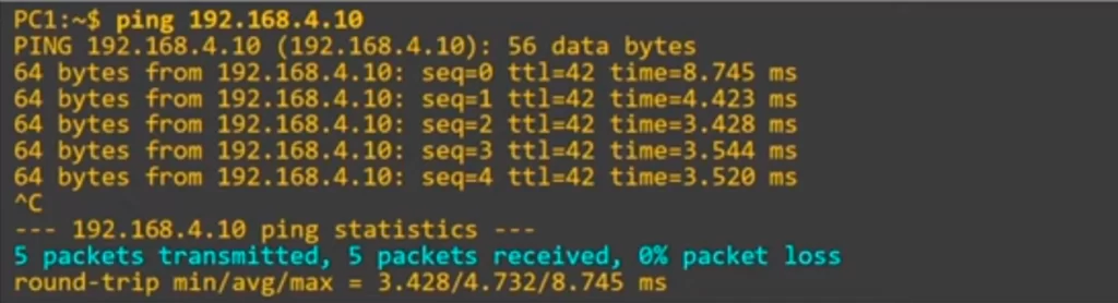
As highlighted, 5 packets were transmitted, 5 packets were received, and 0% packets were lost. If the ping is successful, that means there is two-way reachability. PC1 can reach PC4, and PC4 can reach PC1. If PC1 could reach PC4, but PC4 could not send replies back to PC1, the ping would not work.
Now let’s briefly look at how a packet traveling from PC1 to PC4 is encapsulated, de-encapsulated, and re-encapsulated in different frames as it travels through the network.
When PC1 sends a message to PC4 the Layer 3 destination is PC4’s IP address, 192.168.4.10. However, at Layer 2 the destination MAC address is PC1’s default gateway, which is R1’s G0/2 interface. Now R1 has the packet and it’s R1’s job to forward the packet to the next-hop R3. To do so, R1 encapsulates the packet in a new Ethernet frame. This time the destination of the frame is the next-hop’s MAC address, the MAC address of R3’s G0/0 interface.
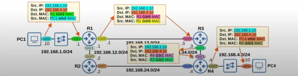
Now R3 has the packet and must forward it to the next hop, R4. To do that, R3 again encapsulates the packet in a new Ethernet frame, and the destination of that frame is the MAC of R4’s G0/1 interface.
Now R4 has the packet, and since R4 is directly connected to the destination network, R4 can forward the packet to PC4. R4 does that by encapsulating the packet in a frame with PC4’s MAC as the destination. This is the only time in the journey that the destination IP and MAC are of the same device. The destination IP is PC4’s IP, and the destination MAC is PC4’s MAC.
The source and destination IPs of the packet do not change throughout the journey, but each time the packet is de-encapsulated and re-encapsulated, the source and destination MAC addresses are different.
Static route configuration (exit interface)
Now we look at another option when configuring static routes. We have not configured any routes on R2 yet, so R2 is used for this demonstration.
When configuring static routes, instead of configuring a next-hop we can configure an exit-interface instead. We specify which interface the router should send the packets out of, rather than telling it the actual IP address of the next hop. For example, if R2 wants to send packets to the 192.168.1.0/24 network, it should send the packets to R1. R2 should send the packets out of its G0/0 interface because that interface is connected to R1.
R2(config)#ip route ip-address netmask exit-interface
Here’s the command: IP ROUTE 192.168.1.0 255.255.255.0 G0/0
There is one more option: you can specify both the exit interface and the next hop.
R2(config)#ip route ip-address netmask exit-interface next-hop
If R2 wants to send packets to the 192.168.4.0/24 network, it should send packets to R4. R2 should send packets out of G0/1, because it’s connected to R4. And the next-hop address is 192.168.24.4, the IP of R4’s G0/0 interface.
Here’s the command. IP ROUTE 192.168.4.0 255.255.255.0 G0/1 192.168.24.4
And here is R2’s routing table now, you can see how each route is displayed.
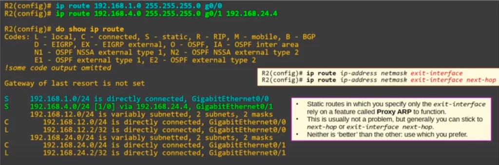
When you specify only the exit interface of the static route, it says the destination network “is directly connected”. Look at the route highlighted in blue, “192.168.1.0/24 is directly connected”. That network is not directly connected to R2, but that’s how it displays in the routing table when you configure only the exit interface.
Static routes in which you specify only the exit-interface rely on a feature called proxy ARP to function. This is usually not a problem, but generally you can stick to specifying next-hop only or both exit-interface and next-hop. Neither configuration method is necessarily better than the others, they are just different methods. Proxy ARP is beyond the scope of the CCNA. However, you should know that when configuring static routes, you can specify the next-hop, the exit-interface, or both.
Default route
*If the router does not have any more specific routes that match a packet’s destination IP address, the router will forward the packet using the default route.
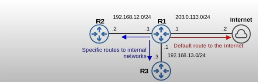
*A default route is often used to direct traffic to the Internet. This is not the only way to use a default route, but it’s a very common use case.
*A default route is basically a route to 0.0.0.0/0. “/0” means that all bits of the netmask are 0, so none of the bits of the address are fixed. 0.0.0.0/0 includes all addresses from 0.0.0.0 to 255.255.255.255.
*The default route is the least specific route possible, because it includes all IP addresses. 0.0.0.0/0 includes over 4 billion IP addresses. On the other hand, a /32 route like a local route is the most specific route possible because it specifies only one IP address.
Let’s look at how to configure a default route on a Cisco router.
In the network below, R1 is connected to R2 and R3, which are other routers owned by the same business.
This is R1’s routing table.
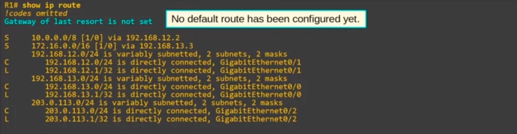
First, notice the highlighted part, “Gateway of last resort is not set”. This means that no default route has been configured yet. “Gateway of last resort” is another name for default gateway.
Notice in R1’s routing table there is a route to 10.0.0.0/8 with R2 as the next hop, and a route to 172.16.0.0/16 with R3 as the next hop. These could be networks used internally by the company.
Here’s how to configure a default route to tell R1 to send all other traffic to the Internet. The structure of the command is the same as any other static route, but the network and netmask should both be all 0s, 0.0.0.0. And that’s it, R1 now has a default route. Let’s check R1’s routing table.
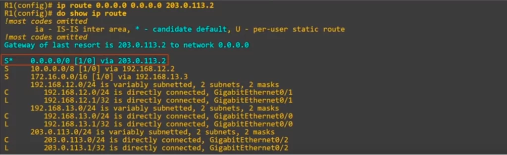
Note the route 0.0.0.0 via 203.0.113.2. There is an asterisk next to the S code. The S code indicates a static route. The asterisk indicates that the route is a default route. In the codes legend it says that the asterisk means “candidate default”, meaning this route is a candidate to become the router’s default route. It’s possible to have multiple candidates. In this case there’s only this one, and note it states “Gateway of last resort is 203.0.113.2 to network 0.0.0.0”, so the route we configured was indeed selected.
Command review
C:\>ipconfig
C:\>ipconfig /all
R#show running-config | include ip route
R#show interfaces [interface-type interface-number]
R(config)#ip route destination-network subnet-mask [exit-interface] next-hop
→to configure a static route on a Cisco router
R(config)#ip route 192.168.3.0 255.255.255.0 192.168.12.3
→configure a static route (example)
R(config)#no ip route 192.168.3.0 255.255.255.0 192.168.12.3
→to delete configuration statement (example)
R(config)#ip route 0.0.0.0 0.0.0.0 next-hop
→to configure a default route
Key learnings
*How to configure an IP address on the router’s interface, and how to read/identify connected and local routes in a routing table via the show ip route command (a review of material covered in the previous lesson).
*How to configure a static IP address for the eth0 network interface of a PC as the default gateway.
*How to configure static routes on Cisco routers to route packets between end hosts in different networks (PC1 and PC4).
*How to configure a default route on a Cisco router.
Practice quiz questions
Quiz question 1
Which of the following commands configures a default route on a Cisco router?
a) R1(config)#ip route 0.0.0.0 0.0.0.0 10.1.1.255
b) R1(config)#ip route 0.0.0.0/0 10.1.1.255
c) R1(config)#ip route 0.0.0.0 255.255.255.255 10.1.1.255
d) R1(config)#ip route 0.0.0.0/32 10.1.1.255
The answer is a), ip route 0.0.0.0 0.0.0.0 10.1.1.255.
Quiz question 2
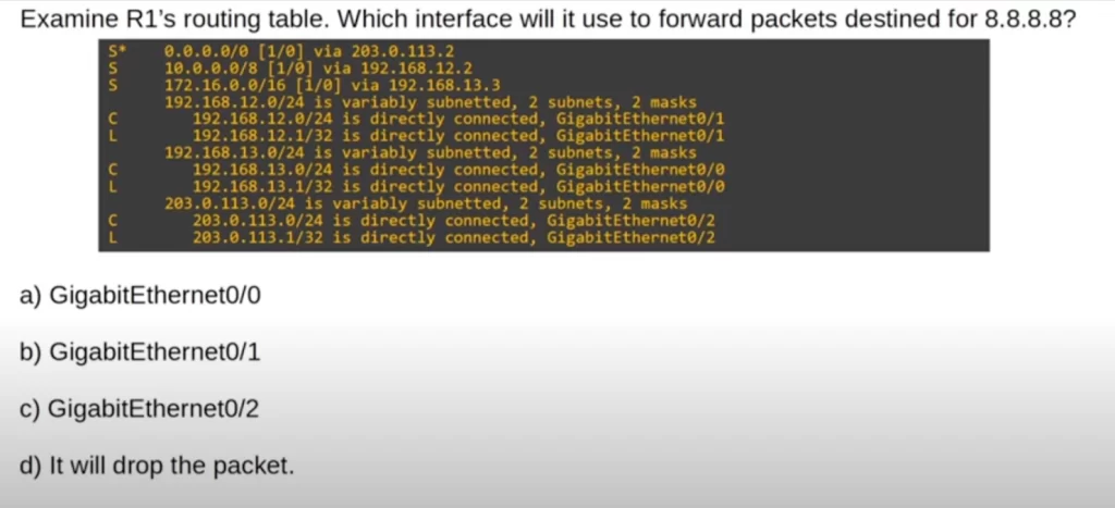
The answer is c), GigabitEthernet0/2.
Quiz question 3
To check the answer for this question, and for two more practice questions for this lesson, visit Jeremy’s Static Routing, Day 11 (part 2), video lesson, cited below.
Configuring static routes – Lab 1
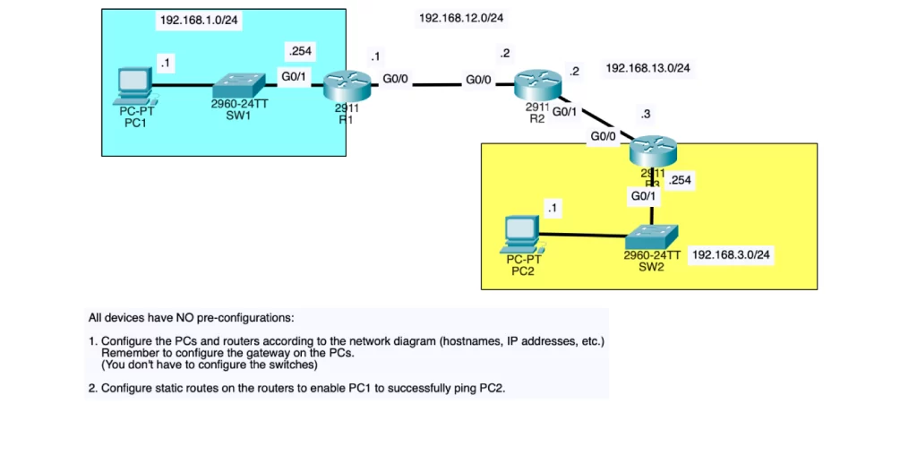
1. Configure the PCs and routers according to the network diagram (hostnames, IP addresses, etc.). Remember to configure the gateway on the PCs. (You don’t have to configure the switches.)
1.1. Set the default gateway and IP address for each of PC1 and PC2
1.2. On routers 1, 2, and 3, set the hostname and configure the interfaces.
For example, on R1 configure the interfaces:
1) Set the IP address on g0/1, add a description, and enable the interface.
2) Set the IP address on g0/0, add a description, and enable the interface.
3) Check with show ip interface brief.
2. Configure static routes on the routers to enable PC1 to successfully ping PC2.
Step 1: consider what static routes you need to configure. You need two-way reachability, i.e., R1, R2, and R3 each need a route to both PC1’s (192.168.1.0/24) and PC2’s (192.168.3.0/24) networks.
Step 2: configure the routes.
Step 3: check the configured static route with show ip route.
>R1:
-has a route to 192.168.1.0/24.
-needs a route to 192.168.3.0/24.
R1(config)#ip route 192.168.3.0 255.255.255.0 192.168.12.2
>R2:
-needs a route to 192.168.1.0/24.
-needs a route to 192.168.3.0/24.
R2(config)#ip route 192.168.1.0 255.255.255.0 192.168.12.1
R2(config)#ip route 192.168.3.0 255.255.255.0 192.168.13.3
>R3:
-has a route to 192.168.3.0/24.
-needs a route to 192.168.1.0/24.
R3(config)#ip route 192.168.1.0 255.255.255.0 192.168.13.2
Troubleshooting static routes – Lab 2
Troubleshoot a configured network that has some problems – using the same network topology of the previous lab.
PC1 and PC2 are unable to ping each other. There is one misconfiguration on each router. Find and fix the misconfigurations. You have successfully completed the lab when PC1 and PC2 can ping each other.
Step 1: confirm the problem, can PC1 ping PC2? No.
Step 2: check the PCs configs, using:
C:\>ipconfig and/or C:\>ipconfig /all
Can PC1 ping its default gateway? Yes, no problem.
Step 3: go on to R1 to investigate and fix configs/connectivity problems.
→check if the interface configs, the IP addresses, are OK using show ip int br. No problem.
→check the routing table using show ip route, to check C, L, and S routes.
Notice: static route to 192.168.3.0/24 is 192.168.12.3 when it should be 192.168.12.2.
You can also check that wrong static route config using show running-config, thus:
R1#show running-config | include ip route
To fix the wrong configuration:
R1(config)#no ip route 192.168.3.0 255.255.255.0 192.168.12.3
This should delete the wrong configuration statement. Check with show ip route or with show running-config | include ip route
The wrong configuration statement is gone. Now configure the correct static route.
Step 4: now let’s work on R2.
→show ip int br. No problems.
→check the routing table using show ip route.
Now we can see a wrong static route configuration, it is wrong that g0/0 is the exit interface to reach 192.168.3.0/24.
So again, remove the wrong configuration statement and add the correct one. Do not leave both statements (you don’t want to load balance with this wrong setting, creating problems).
Step 5: now let’s look for the issue on R3.
→show ip int br. We see a problem. 192.168.23.3 should be 192.168.13.3, R3’s g0/0 IP address.
We don’t have to remove the wrong IP address first. A new IP address will overwrite a current IP address, this is unlike when configuring routes.
R3(config)#int g0/0
R3(config-if)#ip address 192.168.13.3 255.255.255.0
Check again with show ip int br and with show running-config. Finally, you can check the routing table with show ip route.
Can PC1 now ping PC2? Yes.
Key references
Note: The resources cited below (in the “Key references” section of this document) are the main source of knowledge for these study notes/this lesson, unless stated otherwise.
Free CCNA | Static Routing | Day 11 (part 2) | CCNA 200-301 Complete Course
Free CCNA | Configuring Static Routes | Day 11 Lab 1 | CCNA 200-301 Complete Course
Free CCNA | Troubleshooting Static Routes | Day 11 Lab 2 | CCNA 200-301 Complete Course
Related content
Compliance frameworks and industry standards
How data flow through the Internet
How to break into information security
IT career paths – everything you need to know
Job roles in IT and cybersecurity
Network security risk mitigation best practices
The GRC approach to managing cybersecurity
The penetration testing process
The Security Operations Center (SOC) career path
Back to DTI Courses


