In the lesson IPv4 address configuration and verification, we learned how to configure IPv4 addresses on router interfaces. This post focuses on the topic of configuring and verifying Cisco switch interfaces. This lesson looks at how switch interfaces are different from as well as similar to router interfaces. We learn how to configure L1 characteristics of switch interfaces such as speed and duplex. This post constitutes Issue 7 of my CCNA 200-301 study notes.
- show ip interface brief command
- show interfaces status command
- Configuring interface speed and duplex
- interface range command
- Ethernet hubs
- CSMA/CD (Carrier-Sense Multiple Access with Collision Detection)
- Speed/duplex autonegotiation on switch/router interfaces
- Interface counters and errors
- Command review
- Key references
You may also be interested in CCNA 200-301 study notes.
show ip interface brief command
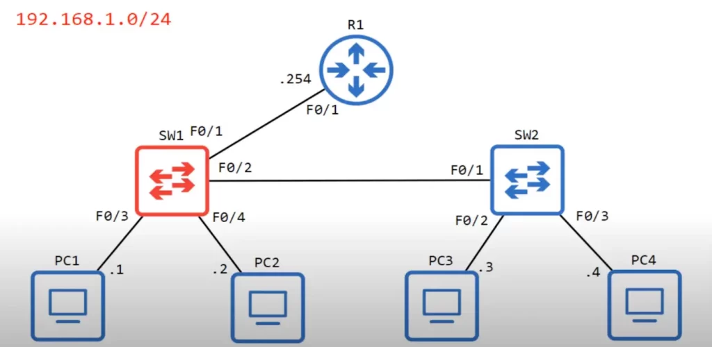
Consider the following network topology. We will focus on SW1 – configuring its interfaces, including F0/1, F0/2, F0/3, and F0/4, which are connected, as well as its remaining interfaces, which are not connected.
Let’s go into the CLI of SW1.
SW1>en
SW1#show ip interface brief
The CLI output fields for the show ip interface brief command on SW1 are identical to the CLI output fields for using this command on a router (see IPv4 address configuration and verification).
As you can see, the four switch interfaces that are connected to devices – FastEthernet0/1, 0/2, 0/3, and 0/4 – have a Status column (which is the L1 status) and a Protocol column (which is the L2 status) up and up or up/up.
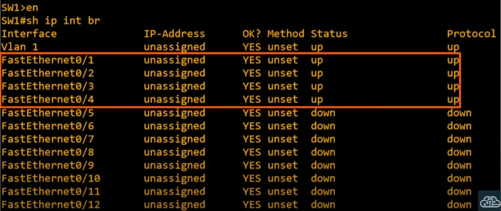
We have not done any configuration on SW1 yet except for the host name. Note the difference between Cisco routers and switches: router interfaces are in an administratively disabled (down/down) state by default, i.e., they have the shutdown command applied. By contrast, switch interfaces do not have the shutdown command applied by default.
If switches are connected to another device they will usually be in the up/up state with no configuration required. A switch interface will be in the down/down state if not connected to another device.
The IP address is unassigned and will remain thus since these are L2 switch ports – they do not need an IP address. Note, in multilayer switching you can assign IP addresses to switches, but we are not discussing this type of configuration in this lesson. We are also ignoring the Vlan 1 interface in this lesson.
Look at the other interfaces, they are not connected to any other devices, so their status is down/down.
Note: in switches, down and down (Status down and Protocol down) are different from administratively down and down in routers. This is because of the shutdown command. Down and down in switches means the interfaces are not connected to another device, not that the interfaces are shutdown.
show interfaces status command
A useful command to check switch interfaces is show interfaces status.
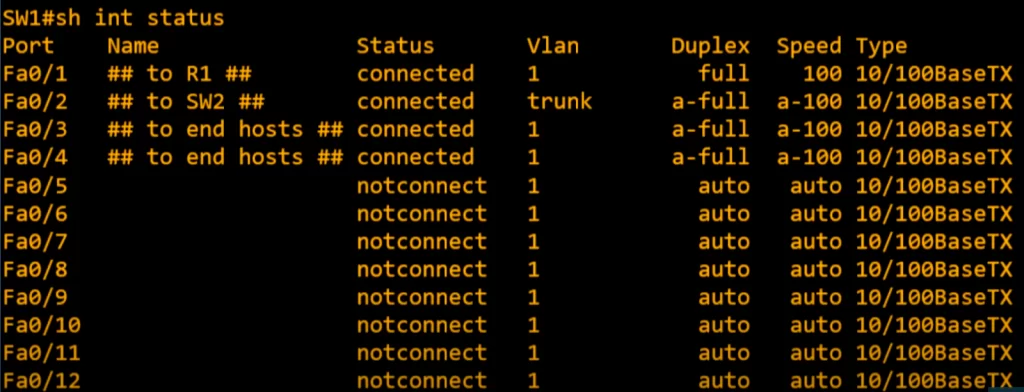
SW1#show interfaces status
Let’s look at the CLI output fields.
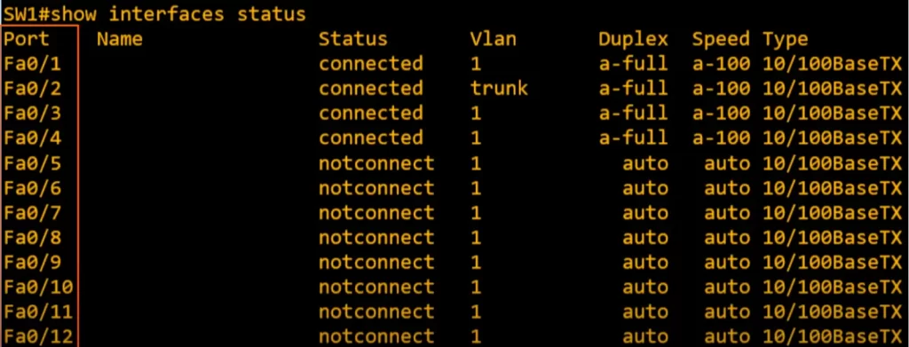
>The Port field lists each interface.
>The Name field is a description field for the interface.
>The Status field – this is different from the Status field of the show ip interface brief.
>Notice the default VLAN is 1. F0/2 interface shows trunk. While an access port can have only one VLAN configured on the interface (it can carry traffic for only one VLAN), a trunk port can have two or more VLANs configured on the interface (it can carry traffic for several VLANs simultaneously).
>The Duplex field indicates whether the device is capable of sending and receiving data concurrently, known as full duplex, or if it is not, then it is called half duplex. If a device is operating at half duplex, if it is receiving a frame, it must wait before sending a frame.
Duplex is auto by default on Cisco switches, meaning a switch will negotiate with the neighboring device and use full duplex if possible. Duplex autonegotiation allows two devices to negotiate speed and duplex settings without us having to manually configure them.
a-full – i.e., “a” stands for auto, meaning the device automatically negotiated a full duplex with the neighboring device.
>The Speed field is also auto by default. Speed refers to the data transmission rate in bits per second. These are Fast Ethernet interfaces capable of speeds ranging from 10 Mbps to 100 Mbps.
a-100 refers to a speed of 100 Mbps auto negotiated with the neighboring device. “auto” means a neighboring device is able to negotiate with the device it is connected to and use the fastest speed both devices are capable of.
>The Type field lists RJ45 interfaces for copper UTP cables. 10/100BaseTX refers to the speed at which the cables can operate (i.e., 10 and 100 Mbps).
Configuring interface speed and duplex
Auto negotiation works well. But let’s manually configure the speed and duplex of interface F0/1.
We enter the interface config mode and then use the speed command.
SW1(config)#int f0/1
SW1(config-if)#speed ?
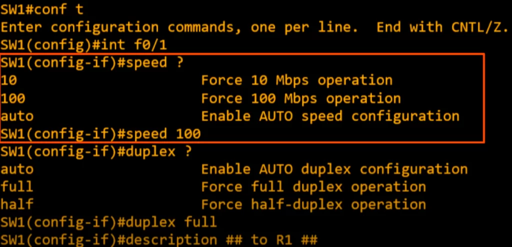
We used the context sensitive help to display the next option. We chose to set the speed at 100 Mbps since R1’s interface is a Fast Ethernet interface also.
SW1(config-if)#speed 100
We then used the command duplex to set the duplex of the interface. We chose to set the duplex to full duplex since SW1 and R1 support it.
SW1(config-if)#duplex ?
SW1(config-if)duplex full
We then configured a description on the interface indicating that it is connected to R1:
SW1(config-if)#description ## to R1 ##
When we use the show interfaces status command again we can see the configured description, speed, and duplex.
The duplex displays full rather than a-full and the speed displays 100 rather than a-100 because they are not auto negotiated anymore.
Regarding the unused interfaces: although the fact that switch interfaces are enabled by default is convenient, this can be a security concern. We should disable the unused interfaces.
interface range command
We do not have to configure each interface one by one – there is a way to configure the eight interfaces at once.
From global config mode, enter an interface range:
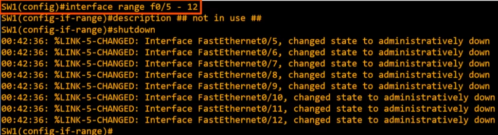
SW1(config)#interface range f0/5 – 12
We are brought to interface range config mode. We enter a description and then shutdown the interfaces. We get a message indicating the interfaces have changed to administratively down.
Note: we do not have to select interfaces in a consecutive range, e.g., if we want to leave interfaces 7 and 8 shutdown we can do this:
SW1(config)#int range f0/5 – 6, f0/9 – 12
SW1(config-if-range)#no shut
Thus F0/7 and F0/8 interfaces would remain down.
Let’s check show interfaces status again. Here is the output:
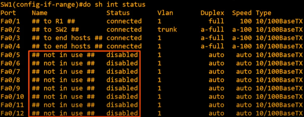
We can see the description of each interface. And Status is disabled. This status is different from the status in show ip interface brief which will now be administratively down (though they mean the same thing).
Ethernet hubs
Half duplex is almost never used in modern networks. Hubs, the predecessors to switches, must operate in half duplex mode to avoid collisions.
A hub is basically a multiport repeater. Hubs are Layer 1 devices that simply amplify and repeat the signal they receive on one port to all other ports. This means that if two devices connected to the same hub try to transmit data at the same time, their signals will collide and be corrupted.
A hub will flood any frame it receives, like a switch does with a broadcast or unknown unicast frame.
To avoid collisions, hubs must operate in half duplex mode. In half duplex mode, devices can only transmit or receive data, not both at the same time. This ensures that only one device can transmit data on the network segment at a time.
All devices connected to a hub are part of what’s called a collision domain. The frames they send could collide with frames sent by any of the other devices connected to the hub.
Ethernet devices use a mechanism called CSMA/CD on half duplex interfaces to detect and avoid collisions.
CSMA/CD (Carrier-Sense Multiple Access with Collision Detection)
CSMA/CD describes how devices using half-duplex listen for activity on a network segment, and then send data only when other devices are not sending. CSMA/CD also describes how a device will react when a collision does occur.
CSMA/CD works by having devices listen to the network segment before transmitting data. If the network segment is clear, the device can transmit its data. If the network segment is busy, the device will wait until it is clear before transmitting.
If a collision occurs, the device that detects the collision sends a jamming signal to inform the other devices that a collision happened. The devices will stop transmitting and wait for a random amount of time before trying to transmit again. This helps to prevent the same collision from happening over and over again.
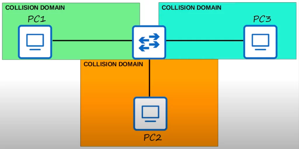
Unlike hubs, which operate at Layer 1, switches operate at layer 2, using layer 2 addressing (MAC addresses) to send frames to specific hosts. Switches will not send two frames to the same host at once.
This network was one collision domain when a hub was used to connect the end devices. There are now three collision domains. Switches operate in full duplex by default.
Speed/duplex autonegotiation on switch/router interfaces
Interfaces that can operate at different speeds (e.g., 10/100 or 10/100/1000) have default settings of speed auto and duplex auto. Interfaces advertise their capabilities to their neighbors. When autonegotiation is enabled, the interfaces will use the advertised capabilities to negotiate the best speed and duplex settings they are both capable of. Let’s look at two scenarios.
1) If autonegotiation is enabled on the device connected to the switch
Here’s a small network, a switch with three PCs connected. Connected to G0/1 is a PC with a regular Ethernet interface. Connected to G0/2 is a PC with a FastEthernet interface. And connected to G0/3 is a PC with a Gigabit Ethernet interface.
An Ethernet interface can run at 10 Mbps, a FastEthernet interface can run at 10 or 100 Mbps, and a Gigabit Ethernet interface can run at 10, 100, or 1000 Mbps.
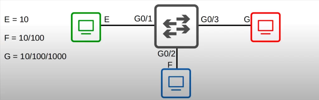
G0/1 and the PC will negotiate to a speed of 10 megabits per second, and full duplex.
G0/2 and the PC will negotiate to a speed of 100 and full duplex.
And G0/3 and the PC will negotiate to speed 1000 and full duplex.
All the PCs can use the maximum speed of their network interfaces, and the switch adjusts the speeds of its interfaces to match. Here, there is no reason to use half-duplex, so they all negotiate to use full-duplex.
2) If autonegotiation is disabled on the device connected to the switch
The switch is trying to autonegotiate, but the other devices are not responding. This is how the switch will respond.
For the speed, the switch will try to sense the speed that the other device is operating at. If it fails to sense the speed, it will use the slowest supported speed (i.e., 10 Mbps on a 10/100/1000 interface).
For duplex, if the switch interface speed is 10 or 100 Mbps, the switch will use half duplex. Otherwise/if the speed is 1000 Mbps or greater, the switch will use full duplex.
Here is an illustration of how this works.
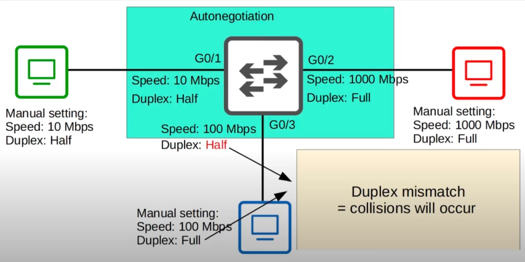
In this case, only the switch is using autonegotiation, and the three PCs have manual, fixed speed and duplex settings. The switch successfully detects the speed that the PCs are using.
>The switch’s G0/1 connected to the green PC: the PC has a speed of 10 Mbps, so the switch detects that and sets its speed to the same value. Because its speed is 10 Mbps, it sets its speed to half duplex.
>The switch’s G0/2 connected to the red PC: the switch senses that the PC is using a speed of 1000 Mbps, so it uses the same speed. Because the speed is 1000 Mbps, it uses full duplex.
>The switch’s G0/3 connected to the blue PC: the switch senses the speed of 100 Mbps. But what about the duplex? Without autonegotiation the switch cannot sense that the PC is using full duplex. So because the speed is 100 Mbps, the switch uses half duplex. This results in a duplex mismatch, which will cause collisions to occur, resulting in poor network performance.
Interface counters and errors
Cisco devices keep various counters regarding the traffic that passes through them such as how many errors have occurred. We will see how to find and analyze these statistics and what kind of errors there are.
You can use the show interfaces command to check counters of errors detected on an interface. Specify the interface when using the command to avoid getting excessive information.
Let’s look at some errors that show up on interfaces that otherwise seem to be working. These errors are not specific to switch interfaces, they include router interface errors.
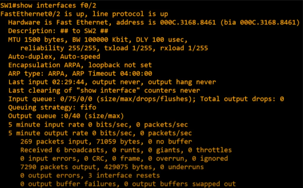
We will focus on some key statistics/counters in the six lowermost lines.
Line 1: note the total number of packets received on the interface and the total number of bytes in those packets (269 and 71059).
Line 2: runts are frames smaller than the minimum Ethernet frame size of 64 bytes. Giants are frames that are larger than the maximum Ethernet frame size of 1518 bytes.
Line 3: CRC counts frames that failed their CRC in the Ethernet FCS trailer. CRC is Cyclic Redundancy Check done via the FCS or Frame Check Sequence in the trailer of an Ethernet frame. It is used to detect errors. Frame: counts frames that have an illegal or incorrect format. Input errors refers to the total of various counters such as the above four.
Line 5: output errors counts frames a device tried to send but failed due to an error.
Command review
SW#show ip interface brief
→to confirm the status and IP address of each interface on the device
SW#show interfaces status
→to see the configured description, speed, and duplex
SW(config-if)#speed {10 | 100 | auto}
→to manually configure the speed of an interface
SW(config-if)#duplex {auto | full | half}
→to manually configure the duplex of an interface
SW(config-if)#description description
→to add a description on an interface
SW(config)#interface range interface-range
→to configure a range of interfaces at once
SW(config-if-range)#description description
SW(config-if-range)#shutdown
SW#show interfaces [interface]
→to check counters of errors detected on an interface. You can specify an interface
Free CCNA | Configuring Interfaces | Day 9 Lab – Notes
Key references
Note: The resources cited below (in the “Key references” section of this document) are the main source of knowledge for these study notes/this lesson, unless stated otherwise.
Free CCNA | Switch Interfaces | Day 9 | CCNA 200-301 Complete Course
Free CCNA | Configuring Interfaces | Day 9 Lab | CCNA 200-301 Complete Course
Other references/resources
Related content
Cisco IOS CLI and device security
Compliance frameworks and industry standards
How data flow through the Internet
How to break into information security
IT career paths – everything you need to know
Job roles in IT and cybersecurity
Network security risk mitigation best practices
The GRC approach to managing cybersecurity
The penetration testing process
The Security Operations Center (SOC) career path
Back to DTI Courses


