This is Part 1 of 2 of subnetting study notes for the CCNA exam. Subnetting is the art and science of dividing a network into smaller networks called subnets. This lesson (Part 1), Classless IPv4 addressing and subnetting, introduces the topic of subnetting and concludes with a subnetting exercise that introduces the FLSM (fixed-length subnet mask) subnetting method. Part 2 of the subnetting study notes, CCNA subnetting exercises, is devoted exclusively to subnetting exercises. We practice how to subnet using both the FLSM and the VLSM (variable-length subnet mask) subnetting methods.
First, the classful IPv4 addressing system is introduced and we learn about the characteristics of the five network classes, A, B, C, D, and E. Next we learn about CIDR (Classless Inter-Domain Routing) and why it is a more efficient method of allocating IP addresses than the discontinued classful addressing system. Next the concept of prefix length is introduced and we look at how the prefix length defines the characteristics of IPv4 classes. Next the case for classless IPv4 addressing is made. We explore why variable prefix lengths improve the efficiency of IP address allocation. Next the topic of subnetting is discussed – what it is and how to do it. We learn how to calculate the number of usable host addresses in a network.
Finally, we start practicing subnetting. A Class C network is divided into 4 subnets using the /26 prefix. Three subnetting methods are used to subnet the network. This post discusses classless IPv4 addressing and subnetting in the context of the CCNA exam. This post constitutes Issue 10 of my CCNA 200-301 study notes.
- CIDR – Classless Inter-Domain Routing
- Classless IPv4 addressing – prefix lengths
- The case for classless IPv4 addressing
- Introduction to subnetting
- Subnetting Exercise 1
- Subnetting trick
- Key references
You may also be interested in CCNA 200-301 study notes.
CIDR – Classless Inter-Domain Routing
Classful network addressing architecture is an obsolete method of allocating IP addresses in IPv4. Classful addressing was introduced in RFC 791 in 1981 as a part of the specification of the Internet Protocol.
Classful addressing divides the IPv4 address space into five classes: A, B, C, D, and E. The first four bits of an IP address determine the class of the address. The classes are assigned different numbers of network bits and host bits.
In a Class C network, for example, the network portion of an IP address is allocated to the first three octets, leaving the last eight bits for host addresses. Only classes A, B, and C can be assigned to a device. Class D is for multicast networking and the Class E address range is reserved for future or experimental purposes.
The IETF (Internet Engineering Task Force) introduced CIDR in 1993 to replace the classful addressing system. Under the now obsolete classful network addressing architecture, the IPv4 addressing convention was governed by rigid rules. CIDR allowed us to be more flexible in how we assign IP addresses. CIDR is a more efficient method of allocating IP addresses.
CIDR notation is a compact representation of an IP address and its associated network mask. CIDR notation specifies an IP address, a slash (/) character, and a decimal number. The decimal number is the count of consecutive leading 1-bits (from left to right) in the network mask.
For example, the IP address 192.168.1.100 with a subnet mask of 255.255.255.0 would be written as 192.168.1.100/24. The /24 indicates that the first 24 bits of the IP address are the network bits, and the remaining 8 bits are the host bits. This means that there are 256 (28) possible IP addresses in this subnet, from 0 to 255.
There are 254 possible (usable) host addresses in a subnet with a prefix length of 24, from 1 to 254. The first address in the subnet is the network address, and the last address is the broadcast address. These addresses cannot be used by hosts.
Classful addressing has two main shortcomings addressed by classless addressing:
1) Inefficient use of address space: the fixed number of network bits and host bits in each class of address leads to inefficient use of address space. The rigidity in IP addressing makes it difficult to efficiently allocate addresses to networks of different sizes. For example, a Class C network with only a few hosts would waste most of its address space.
2) Difficult to manage: classful addressing can be difficult to manage, especially as the size of the Internet grows. This is because routers need to keep track of the different subnet masks in use.
CIDR allows for a variable number of network bits and host bits, which makes it possible to allocate IP addresses more efficiently. With CIDR, network administrators can assign subnet masks that are more appropriate for the size of their network, which results in a more efficient use of IP addresses.
CIDR is also a more efficient way to route IP packets. With classful addressing, routers had to keep track of all of the different subnet masks in use. With CIDR, routers only need to keep track of the CIDR prefixes of the networks that they know about. This makes it easier for routers to route IP packets, which results in a more efficient network.
Classless IPv4 addressing – prefix lengths
Prefix length refers to the number of bits in the network portion of an IP address. For example, the IP address 192.168.1.100/24 has a prefix length of 24, which means that the first 24 bits of the address are the network bits. The remaining 8 bits are the host bits.
| Class | First octet | First octet numeric range | Prefix length |
| A | 0XXXXXXX | 0-127 | /8 |
| B | 10XXXXXX | 128-191 | /16 |
| C | 110XXXXX | 192-223 | /24 |
Class A addresses have a /8 prefix length, meaning, the first octet identifies the network and the other three octets are used for individual hosts within the network.
The different prefix lengths give different characteristics to these IPv4 classes.
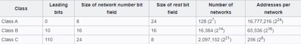
In Class A, only 128 networks are available (27) – actually two less than that: the block 127.0.0.0/8 is assigned for use as the Internet host loopback address, and 0.0.0.0/8 is a default route. Because only the first octet of a Class A address is used for the network ID, there are three octets available for host addresses within each Class A network: 224.
To clarify, a Class A network has 128 networks available (2^7) because the leading bit is always zero, otherwise there would be 256 possible networks or 2^8. A Class B network has 2^14 networks available because the leading 2 bits are fixed, leaving 14 bits out of 16 for network addresses. A Class C network has 2^21 networks available because the leading 3 bits are fixed, leaving 21 out of 24 for network addresses.
The first octet of a Class A network has the numeric range of 0-127 because the leading 8 bits can range from 00000000 to 01111111 or 0-127 in decimal. You get the idea.
The case for classless IPv4 addressing
In classful network addressing architecture, the prefix length is fixed for each class of address. For example, all Class A networks have a prefix length of 8, all Class B networks have a prefix length of 16, and all Class C networks have a prefix length of 24. Classful addressing is inefficient because it does not allow for a fine-grained allocation of IP addresses.
CIDR removed the requirements to allocate precisely 8, 16, and 24 bits to network addresses in Class A, B, and C respectively. CIDR allows for a variable number of network bits and host bits, which makes it possible to allocate IP addresses more efficiently. With CIDR, the prefix length can be any value between 1 and 32.
This flexibility in CIDR permits the accommodation of more hosts with an IP address block and reduces waste of IP address space.
For example, a network administrator can create a subnet with a prefix length of 20, which means that the network will have 4094 possible host addresses (2^12 – 2). This is much more efficient than a Class C network, which only has 256 possible host addresses.
A Class C network with only a few hosts would waste most of its address space. Consider the following point-to-point network connecting two routers, R1 and R2. We should use a Class C network for this topology since we do not need a large address block. The IANA (Internet Assigned Numbers Authority) assigns IPv4 addresses to companies based on their size. A small company is likely to receive a Class C network.
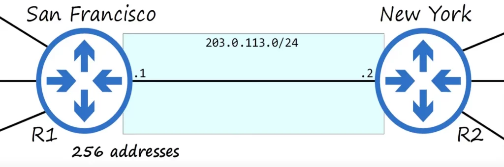
In Class C networks, there are only 256 possible host addresses per network (28). Subtract one for the network address (203.0.113.0), subtract another for the broadcast address (203.0.113.255), subtract a third for R1’s address (203.0.113.1), and subtract a fourth for R2’s address (203.0.113.2). So we have used four addresses and wasted 252 addresses.
To create a subnet, we borrow bits from either the host portion or the network portion of an IP address. When we borrow bits from the host portion, we are creating more subnets with fewer hosts per subnet. When we borrow bits from the network portion, we are creating fewer subnets with more hosts per subnet.
The decision of whether to borrow bits from the host portion or the network portion depends on the specific needs of the network. If we need to create a large number of small subnets, we would borrow bits from the host portion. If we need to create a small number of large subnets, we would borrow bits from the network portion.
Introduction to subnetting
A subnet mask (sometimes “submask” or “mask”) is a 32-bit number created by setting network bits to 1s and host bits to 0s. In this way, the subnet mask separates the IP address into the network and host portions.
You may want to review how to convert between dotted decimal and binary: CCNA math.
The following figure shows the binary layout for the 203.0.113.0/24 network (the binary numbers appear above the dotted decimal numbers). The subnet mask for this /24 network is shown under the network address.
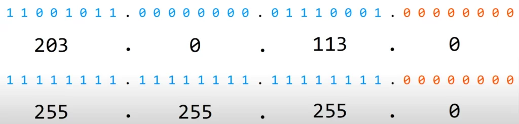
In a /24 network the number of usable host addresses after subtracting the network and broadcast addresses is 254. Recall, network and broadcast addresses cannot be assigned to a device.
The formula to calculate the number of usable addresses in a network is 2n – 2, where n = number of host bits.
Since there are 8 host bits (in orange) in a /24 network, there are 254 usable addresses: 28 – 2 = 256 – 2.
So if we use the /24 prefix length for the 192.168.1.0 network we can create as much as 254 hosts. If we use this prefix length for only 45 hosts, for example, we would be wasting 209 IP addresses.
To create subnets we have to borrow bits from the host portion. With a /25 mask, the network portion (blue) “borrows” one bit (purple) from the host portion (orange) thus extending the network portion into the host portion by one bit (leaving 7 bits for the host addresses) – and we can thus create more networks or subnets with the 203.0.113.0/24 address block.
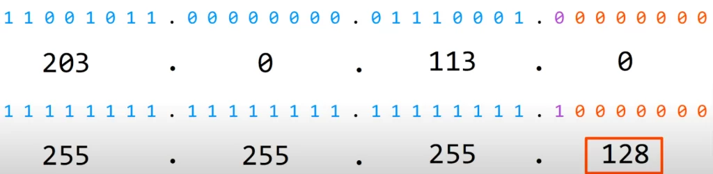
The number of usable addresses is 27 – 2 = 126. We only need two addresses for R1 and R2, so we are wasting 124 addresses with this arrangement. With the /24 prefix length we were wasting 252 addresses.
If we use a /30 prefix length (borrowing six bits from the host portion):
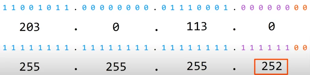
We have two host bits and two usable addresses (four total addresses): 22 – 2 = 2.
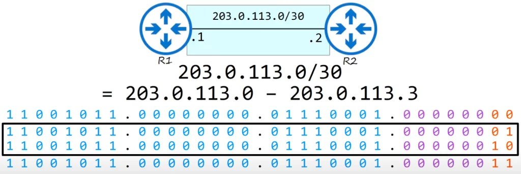
Thus the remaining addresses in the 203.0.113.0/24 address block (203.0.113.4 – 203.0.113.255) are now available for use in other subnets.
If we use a /31 prefix length we would have one host bit and 0 usable addresses. But in a point-to-point connection between two routers it is possible to use a /31 mask since there is actually no need for a network address and a broadcast address.
The /32 prefix length is used when you want to create a static route to one specific host.
CIDR notations for various subnet masks for a Class C network:
| Dotted decimal | CIDR notation |
| 255.255.255.0 | /24 |
| 255.255.255.128 | /25 |
| 255.255.255.192 | /26 |
| 255.255.255.224 | /27 |
| 255.255.255.240 | /28 |
| 255.255.255.248 | /29 |
| 255.255.255.252 | /30 |
| 255.255.255.254 | /31 |
| 255.255.255.255 | /32 |
Subnetting Exercise 1
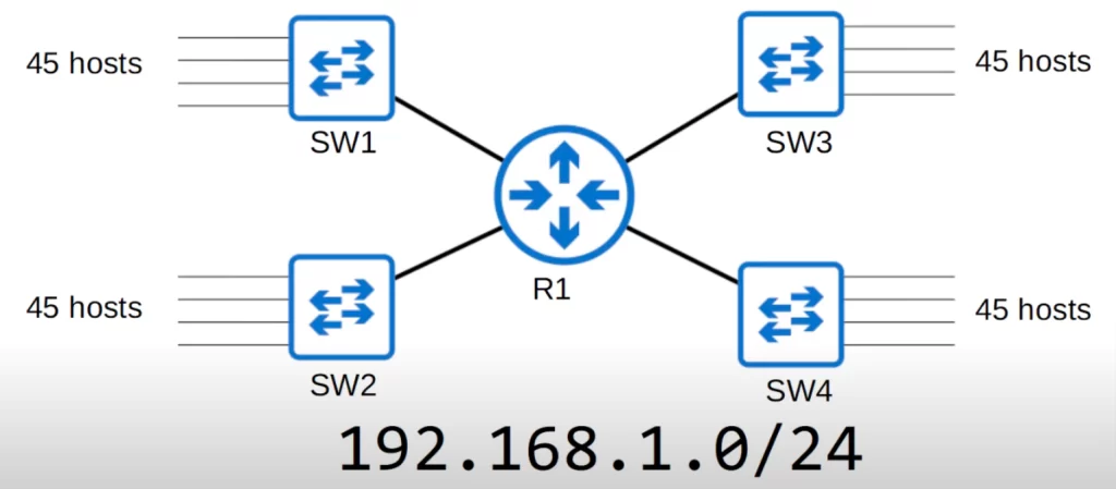
In the following topology there are four networks connected to R1, with many hosts connected to each switch. There are 45 hosts per network. R1 needs an IP address in each network. R1’s address is included in that 45 host number.
You have received the 192.168.1.0/24 network. You must divide the network into four (equal-size) subnets that can accommodate the number of hosts required (45 per network).
Hint: find the broadcast address of Subnet 1. The next address is the network address of Subnet 2. Repeat the process for Subnets 3 and 4.
First off, are there enough addresses in the 192.168.1.0/24 network? We need 45 hosts per network, including R1. Remember, each network has a network and a broadcast address. So we really need 47 addresses per subnet.
47×4 = 188 hosts.
The total number of hosts possible for a Class C network is 28 = 256. So there’s no problem in terms of the number of hosts – there are enough addresses to accommodate 47 hosts per network.
*How to calculate the subnets we need to create
We need four equal-size subnets each with enough room for at least 45 hosts.
>If we use a /30 prefix length: the 192.168.1.0 network with a /30 mask can be written out as follows:
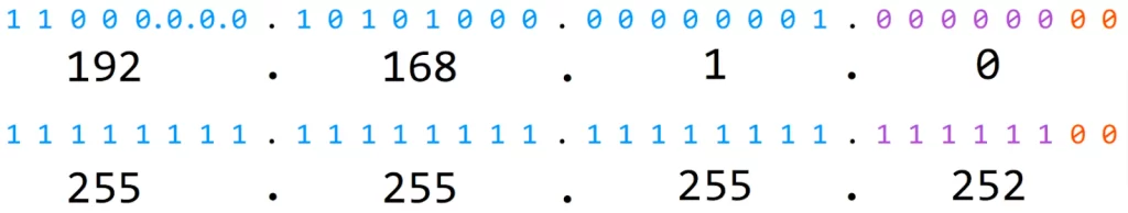
There are 30 network bits and 2 host bits – so, there are only 2 usable host addresses within this subnet: 2^2 – 2 = 2. Not even close to what we want.
>In a /29 mask we would have three host bits and six usable addresses or 23 – 2 = 6. No way José.
>In a /28 prefix length we would have four host bits, so, 24 – 2 = 14 usable addresses.
>In a /27 mask we would have five host bits, so, 25 – 2 = 30 usable addresses.
>In a /26 prefix length the number of usable addresses is 26 – 2 = 64 – 2 = 62.
It looks like we have our prefix length (note: 64 x 4 = 256).
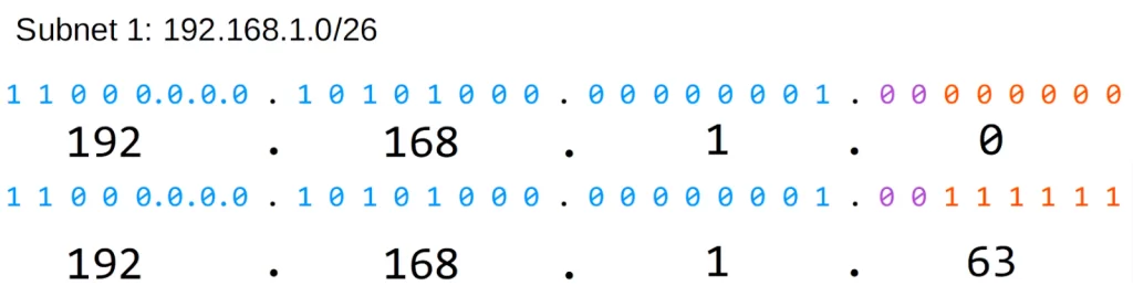
>We can assign the block of 192.168.1.0/26 to Subnet 1.
The IP address range for this block is 192.168.1.0 – 192.168.1.63.
We still have 192.168.1.64 – 192.168.1.255 for the other subnets.
Note, the broadcast address for Subnet 1 is 192.168.1.63. The broadcast address is the highest address in a subnet’s address range.
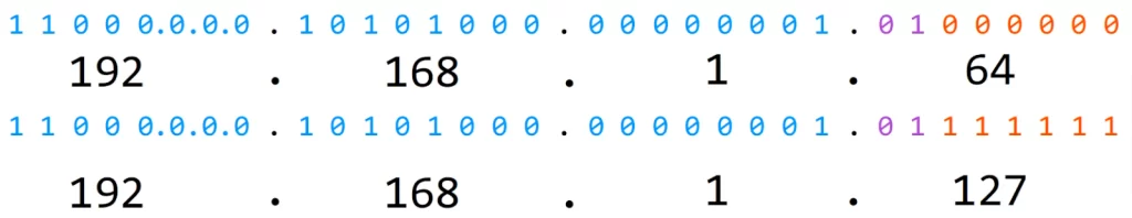
>So the next subnet block is 192.168.1.64 which is the network address of Subnet 2.
So to calculate the IP address range for the second block: 63 + 64 = 127.
So Subnet 2 IP address range is 192.168.1.64 – 192.168.1.127.
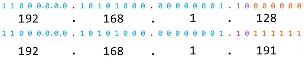
>So Subnet 3 block is 192.168.1.128 which is the network address of Subnet 3.
127 + 64 = 191
So Subnet 3 IP address range is 192.168.1.128 – 192.168.1.191.
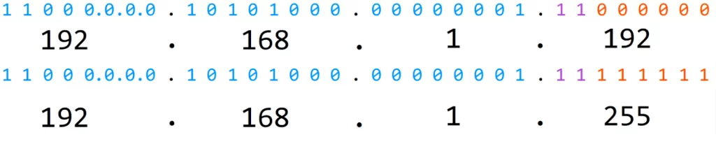
>So Subnet 4 block is 192.168.1.192 which is the network address of Subnet 4.
191 + 64 = 255
So Subnet 4 IP address range is 192.168.1.192 – 192.168.1.255.
Here is another way to think about this.
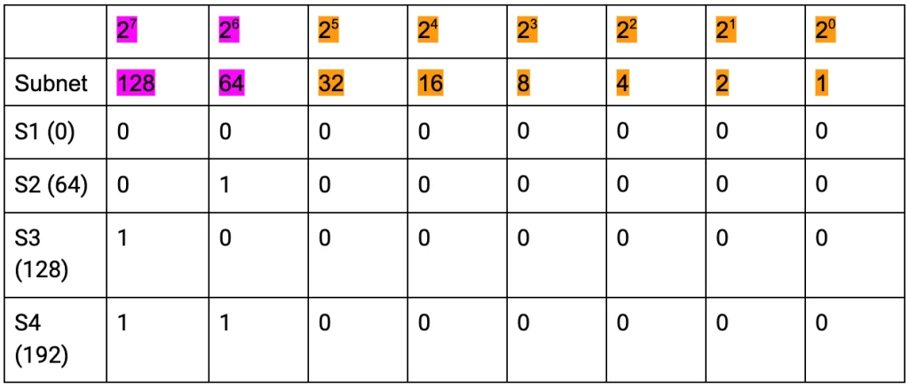
>To find the broadcast address for Subnet 1, set all the bits in the host portion to 1 and convert the binary value to dotted decimal. So the broadcast address for Subnet 1 is 192.168.1.63.
>So Subnet 2 will be 192.168.1.64/26. Here it is in binary (64 in binary: 01000000). To find the broadcast address for Subnet 2 we change all the host bits to ones and convert to dotted decimal. Subnet 2 IP address range is 192.168.1.64 – 192.168.1.127.
>That means that Subnet 3 is 192.168.1.128/26. Write it out in binary then change all host bits to ones and again convert to dotted decimal format to find the broadcast address. Note 128 in binary is 10000000. The broadcast address for Subnet 3 is 192.168.1.191, and the address range for this subnet is 192.168.1.128 – 192.168.1.191.
>And the fourth block network address of Subnet 4 is 192.168.1.192/26. Here is the network address for Subnet 4 in binary. Again we change the host bits to ones to calculate the broadcast address. Notice the borrowed bits (purple) are all ones – we’ve exhausted the number of possible subnets and IP addresses in this prefix range. So Subnet 4 IP address range is 192.168.1.192 – 192.168.1.255.
Subnetting trick
Looking at the last octet of the IP address 192.168.1.0/26 – the host portion is colored in orange and the network portion (the 2 borrowed bits) in purple. To find the next subnet address we just add 64.
Key references
Note: The resources cited below (in the “Key references” section of this document) are the main source of knowledge for these study notes/this lesson, unless stated otherwise.
Free CCNA | Subnetting (Part 1) | Day 13 | CCNA 200-301 Complete Course
Free CCNA | Subnetting (Part 2) | Day 14 | CCNA 200-301 Complete Course
Related content
Compliance frameworks and industry standards
How data flow through the Internet
How to break into information security
IT career paths – everything you need to know
Job roles in IT and cybersecurity
Network security risk mitigation best practices
The GRC approach to managing cybersecurity
The penetration testing process
The Security Operations Center (SOC) career path
Back to DTI Courses


