This is Part 1 of 3 of VLANs study notes for the CCNA exam. In this lesson we begin learning how to configure VLANs (Virtual Local Area Networks) on Cisco switches. More specifically, we look at how to configure and verify default VLANs and access ports. We look at the processes involved in configuring access ports on Cisco switches: creating the VLAN in the switch’s VLAN database, and assigning the switch port to a VLAN. First we discuss what is a broadcast domain and why it is not the same as a subnetwork. We then discuss the purpose of VLANs in a network. Then we learn how to create and configure VLANS.
Part 2 focuses on configuring trunk ports on Cisco switches, and configuring the router interface with subinterfaces each assigned a unique VLAN ID, in a router on a stick (ROAS) topology. Part 3 focuses on configuring native VLANs on a router (ROAS), and configuring inter-VLAN routing using Layer 3 switches. This post constitutes Issue 12 of my CCNA 200-301 study notes.
- What is a LAN
- Broadcast domains
- What is a VLAN
- Configuring access ports on Cisco switches
- Command review
- Key references
You may also be interested in CCNA 200-301 study notes.
What is a LAN
A local area network (LAN) is a group of devices (servers, routers, switches, etc.) in a small geographical area, such as a home, school, or office building. The devices connected to a LAN can access and share data and resources, such as printers and scanners, anywhere on the network.
LANs can be wired or wireless. Wired LANs usually use Ethernet cables and switches, while wireless LANs use Wi-Fi routers and access points. Some LANs can use both wired and wireless connections for different devices or purposes. For example, a home network may have a wired connection for a desktop computer and a wireless connection for a laptop or smartphone.
LANs can be classified into two types: client/server LANs and peer-to-peer LANs. A client/server LAN consists of several devices (the clients) connected to a central server. The server manages file storage, application access, device access, and network traffic. A client can be any connected device that runs or accesses applications or the Internet. A peer-to-peer LAN, on the other hand, does not have a central server. Instead, each device acts as both a client and a server, sharing resources and data directly with other devices on the network.
LANs can be connected to other LANs or wide area networks (WANs) via routers or gateways to form larger networks that span multiple locations or regions.
A LAN is a single broadcast domain, including all devices in that broadcast domain.
Broadcast domains
A broadcast domain is a group of devices which will receive a broadcast frame (having a destination MAC of FFFF.FFFF.FFFF) sent by one of the devices in the domain.
How many broadcast domains are in the following network? Four.
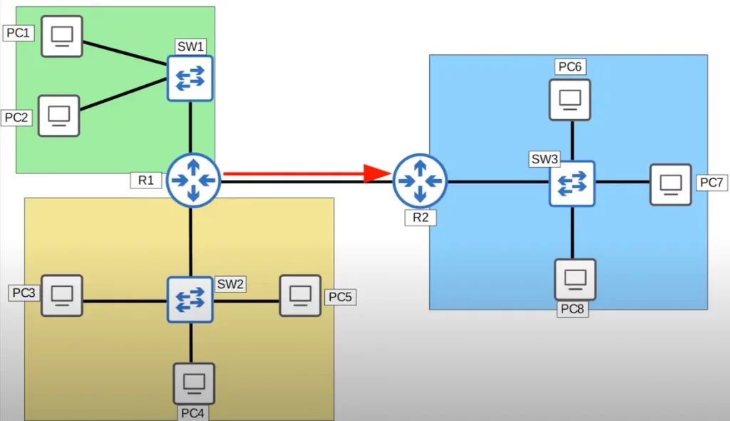
PC6, PC7, PC8, SW3, and one of R2’s interfaces constitute one broadcast domain (the blue compartment). If PC6 sends a broadcast frame, SW3 will receive it and flood it to PC7, PC8, and R2. (R2 will not forward the frame. A router will receive a broadcast frame but will not forward it to other networks.)
There are three more broadcast domains, the yellow compartment, the green compartment, and the connection between R1 and R2. If R1 sends a broadcast frame out of its interface which is connected to R2, the frame will be received only by R2.
What is a VLAN
A virtual LAN (VLAN) is a logical grouping of devices on a switch, creating a virtual LAN. VLANs allow you to segment your network and improve security. For example, you could create a VLAN for each department in your company, or you could create a VLAN for each type of traffic, such as voice or data.
A VLAN is essentially a way to logically split a Layer 2 broadcast domain, to make multiple separate broadcast domains.
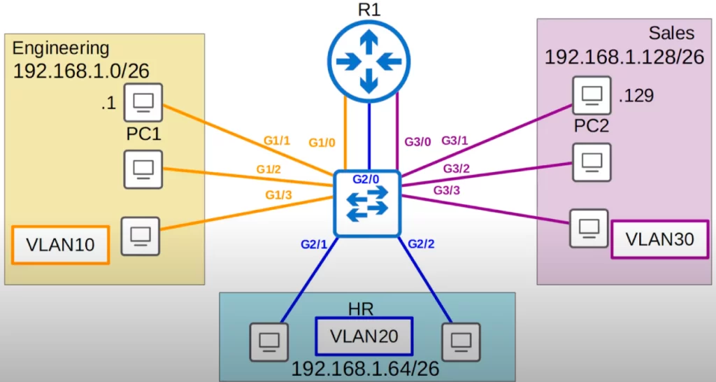
Here is a small LAN of a company.
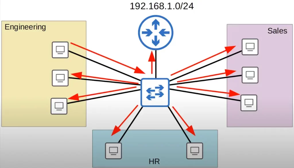
There are three main departments in this company: engineering, sales, and HR. The company is using the 192.168.1.0/24 network for this LAN.
Let’s say a PC in the engineering department sends a broadcast message intended for other PCs in the engineering department. Since it’s a broadcast message, the switch will flood it out of all interfaces. Not only will the PCs in the engineering department receive the broadcast, all PCs, as well as the router, will receive the broadcast.
For both security and network performance purposes, this is not necessarily the best setup. It would be best to split up these departments into separate subnets.
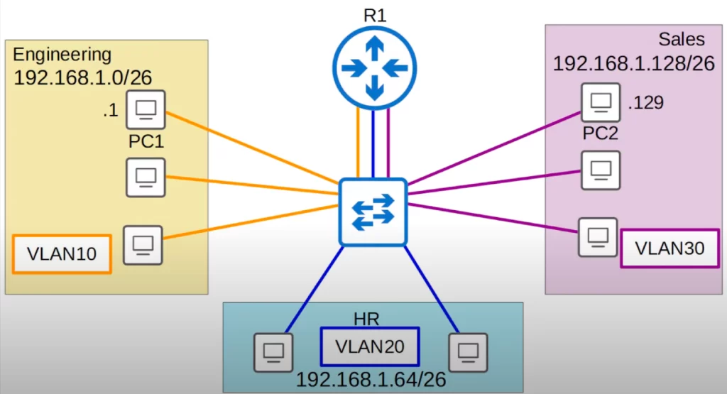
So let’s split up these departments into separate subnets: 192.168.1.0/26 for the engineering department, 192.168.1.64/26 for the HR department, and 192.168.1.128/26 for the sales department.
Houston, we have a problem.
The router is going to need an IP address in each subnet, so it will need one interface in each subnet. So let’s replace the single connection between the switch and router with three separate connections, one in each subnet. (There is a more efficient way of doing this, using a trunk link instead of using three separate interfaces. See VLANs Part 2.)
Let’s say a PC in the engineering department, PC1, has an IP address of 192.168.1.1, and a PC in the sales department, PC2, has an IP address of 192.168.1.129. If PC1 sends some data to PC2, PC1 will recognize that PC2 is in a different subnet than its own, so PC1 will set the destination MAC address to its default gateway, R1.
PC1 will forward the frame to the switch, which will send it to R1, which will then change the source MAC to its own MAC, and the destination MAC to PC2’s MAC. R1 will then forward the frame back to the switch, which will then forward it to the destination, PC2.
Instead of PC1 being able to send traffic directly to PC2, we forced it to send the traffic through R1 first, where we would have configured some security policies to control what traffic is allowed to pass between subnets. So you may think the problem is now solved.
Houston, we still have a problem.
What if the frame is a broadcast or unknown unicast frame? The switch will flood the frame out of all interfaces. For example, PC1 in the engineering department wants to send a broadcast frame. The source IP is PC1’s IP, and the destination IP is its subnet’s broadcast address. So this is a broadcast frame intended for the engineering department. The source MAC is PC1’s, and the destination is the broadcast MAC address of all F’s.
So what’s the problem? Remember that a switch is only aware up to Layer 2. It looks at Layer 2 information like source and destination MAC addresses only, it does not care about Layer 3 and Layer 4. So even though there are three separate subnets in our topology the switch does not know that. PC1 will send the frame to the switch, the switch will see the destination MAC address of all F’s, and then flood the frame.
Although we separated the three departments into three subnets, meaning they are separated at Layer 3, they are still in the same broadcast domain, the same Layer 2 network, or the same LAN.
One possible solution is to buy a separate switch for each department. However, this would not be an optimal or economical solution. Another solution is to use VLANs. Although the PCs are all in the same LAN, we can use VLANs to separate them at Layer 2.
Two ways to split a LAN into smaller LANs:
1) Using routers: To split a LAN into smaller LANs using routers, you will need a router and a switch. You will need to connect the router to the switch and then configure the router to create separate networks for each group of devices connected to the switch. Once you have done this, the devices connected to the different ports on the switch will be able to communicate with each other, but they will not be able to communicate with devices that are connected to the router’s other ports.
2) Using VLANs: VLANs are logical networks that exist on a single physical network. They are created by assigning different VLAN IDs to different ports on a switch. This allows you to separate devices on the same physical network into different logical networks.
To split a LAN into smaller LANs using VLANs, you will need a switch that supports VLANs. You will also need to create the VLANs and assign the ports on the switch to the VLANs. Once you have done this, the devices connected to the ports that are assigned to the same VLAN will be able to communicate with each other, but they will not be able to communicate with devices that are connected to ports that are assigned to different VLANs.
How do we assign end hosts to VLANs?
We configure the switch interface to be in a specific VLAN, and then the end host connected to that interface is part of that VLAN. The switch will consider each VLAN as a separate LAN, and will not forward traffic between VLANs, including broadcast or unknown unicast traffic.
We will assign the engineering department to VLAN10, the HR department to VLAN20, and the sales department to VLAN30.
After setting up these three VLANs, if PC1 sends a broadcast frame, after the frame arrives at the switch, it will be forwarded to all interfaces in the same LAN. Because the broadcast arrived on an interface configured in VLAN10, the switch will only forward the frame to other interfaces in VLAN10.
If PC1 wants to send this same unicast frame to PC2, PC1 will send the unicast frame to the switch, which will send it to the router, which will change the source and destination MAC addresses and send it back to the switch, which will send it to its destination.
Switches do not forward traffic directly between hosts in different VLANs. The switch must send the traffic through a router. The switch does not perform inter-VLAN routing.
Traffic arriving on a switch’s VLAN10 interface is forwarded to other hosts configured on a VLAN10 interface, out of a VLAN10 interface. Likewise, traffic that arrives on a VLAN30 interface is forwarded out of a VLAN30 interface.
A switch will never forward traffic directly between two VLANs. First of all, the hosts are in separate subnets, so PC1 itself will send the traffic to its default gateway, R1. But even if PC1 and PC2 were in the same subnet, the switch would not forward the traffic from PC1 to PC2 because they are in separate VLANs. A switch will not forward frames between VLANs directly, it must send the frames to a router first.
If we use the command ping 255.255.255.255 on PC1, which sends a ping with the destination MAC address of all F’s, the broadcast MAC address, the broadcast will only reach hosts in VLAN10.
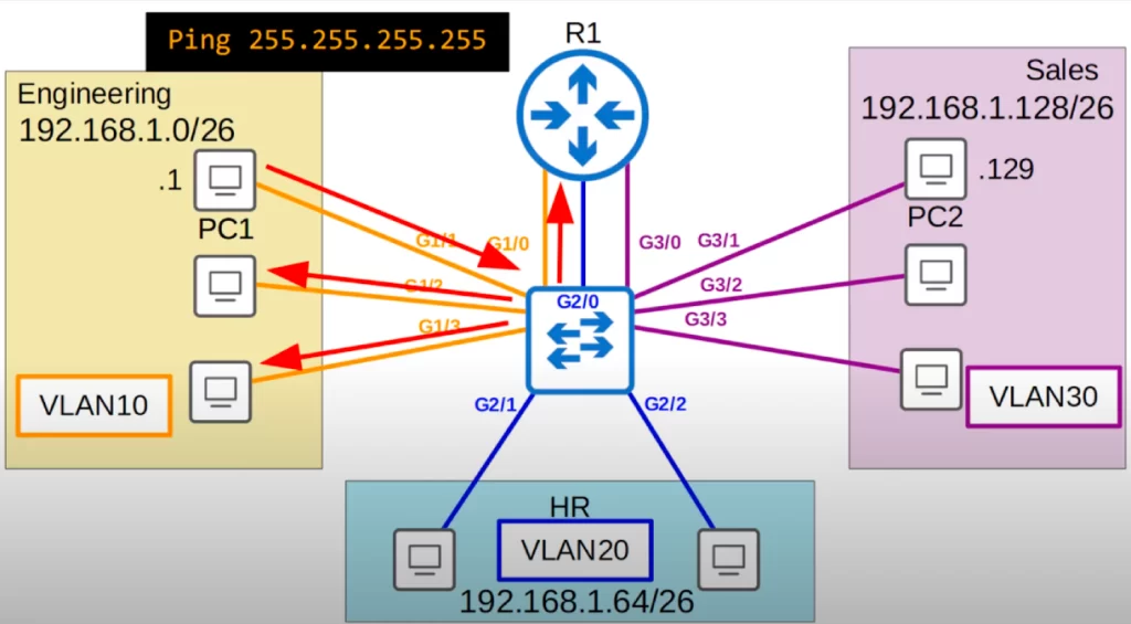
Likewise, if we use the same ping command on PC2, the broadcast will only reach PCs in VLAN30.
A bit of review.
*The above network topology: there is a single switch, and three VLANs. All of the switch interfaces are access ports which belong to a single VLAN, either VLAN10, VLAN20, or VLAN30. Three interfaces are used to connect to the router, one for each VLAN.
An access port is a switchport which belongs to a single VLAN, and usually connects to end hosts such as computers, printers, and servers. It is called an access port because it gives the end hosts access to the network.
There is another important type of switchport called a trunk port. Trunk ports carry traffic for multiple VLANs. They use a tagging mechanism to identify which VLAN each frame belongs to. This allows switches to route traffic to the correct VLANs. Trunk ports are typically used to connect switches together to create a larger network. Trunk ports are covered in parts 2 and 3 of these VLANs study notes.
*VLANs are logically isolated networks within a physical network. VLANs are configured on switches on a per-interface basis.
*VLANs logically separate end hosts at Layer 2. Although the hosts in the above sample topology are physically connected to the same switch, and therefore in the same broadcast domain, we used VLANs to logically separate them, and put them in separate broadcast domains.
*VLANs help improve network performance and network security. VLANs help to reduce unnecessary broadcast traffic, which helps prevent network congestion and therefore improve network performance. Limiting broadcast and unknown unicast messages also improves network security, since these messages will not be received by devices outside of the VLAN.
Configuring access ports on Cisco switches
Let’s configure access ports on a Cisco switch and assign them to a specific VLAN.
Let’s begin by looking at basic VLAN configuration.
First let’s look at the VLANs that exist by default on a switch.
In this CLI output we used the show vlan brief command. The output displays the VLANs that exist on the switch, and which interfaces are in each VLAN.
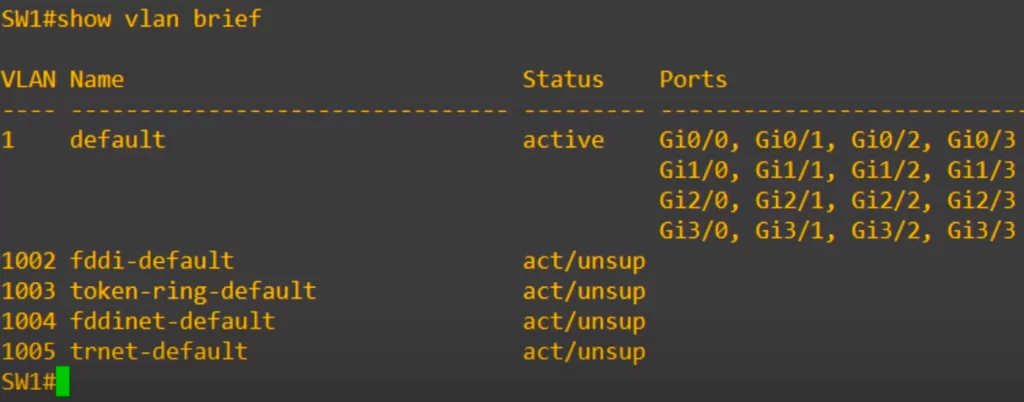
VLAN1 has the name “default.” This is the VLAN that all interfaces are assigned to by default. Even if we do not configure any VLANs, all interfaces are in VLAN1 by default.
Under VLAN1 are four other VLANs, 1002 to 1005, used for FDDI and token ring. These are old technologies that you do not need to know for the CCNA. VLANS 1 and 1002-1005 exist by default and cannot be deleted.
Under the Ports column you can see all the interfaces on this device, from G0/0 to G3/3.
How to assign interfaces to a VLAN
Use the interface range command to configure all the VLAN 10 interfaces at once.
Use the switchport mode access command to set the interface as an access port.
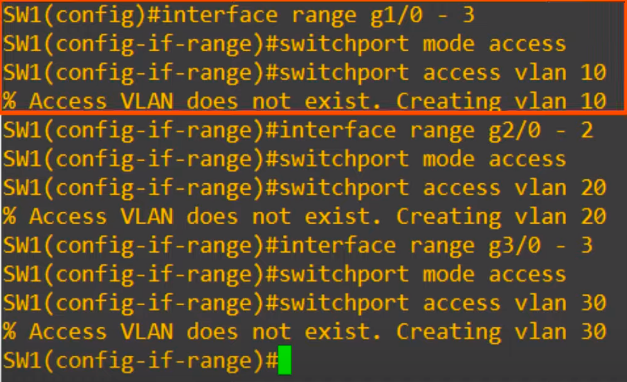
A switchport connected to an end host should enter access mode by default. However, it’s always a good idea to explicitly configure the setting and not rely on autonegotiation of port type.
Next, use the command switchport access vlan, followed by the VLAN number, to assign the VLAN to the port.
We used switchport access vlan 10. Notice the message that appears after entering this command, “% Access VLAN does not exist. Creating vlan 10”.
Because VLAN10 did not exist on the device yet, it was created automatically when we assigned the interface to VLAN10. If we assign a switch interface to a VLAN that does not exist, the switch will create the VLAN.
We will see how to manually create a VLAN in a minute.
Next, again we use the interface range command to configure all of the VLAN 20 interfaces at once. We use the same switchport mode access command, then switchport access vlan 20 to assign the interfaces to VLAN 20. We then configure VLAN30 using the same commands, in the same way.
Using the show vlan brief command again, we can see the three VLANs we created, and the ports we assigned to each VLAN.
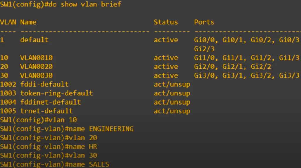
Notice the default names of each VLAN – let’s change those to make them more understandable.
Use the vlan 10 command to enter configuration mode for VLAN 10.
SW1(config)#vlan 10
This is also the command to create a VLAN. But in this case, it was already automatically created when we assigned the interfaces to the VLAN.
Next, we assign the VLAN name with the command name ENGINEERING.
SW1(config-vlan)#name ENGINEERING
Then we do the same for VLAN 20 (HR) and VLAN 30 (sales).
Finally, we confirm the configurations with show vlan brief. You will notice that the names have been changed to ENGINEERING, HR, and SALES.
Remember:
*By default, before configuring VLANs, each router interface and everything connected to it are in one broadcast domain. If no VLANs have been configured, all hosts/interfaces are in the same default VLAN, VLAN1.
*VLANs logically separate hosts and put them in separate broadcast domains. Each configured VLAN constitutes a broadcast domain (the connection between two routers is also a broadcast domain).
Command review
SW#show vlan brief
→to display the VLANs that exist on the switch and which interfaces are in each VLAN
SW(config)#interface interface-name interface-number
→to configure one VLAN interface (to enter interface configuration mode)
SW(config)#interface range interface-range
→to configure a range of VLAN interfaces at once
SW(config-if-range)#switchport mode access
→to set the interface as an access port
SW(config-if-range)#switchport access vlan vlan-number
→to assign the VLAN to the port, and to create the VLAN if assigning an interface to a VLAN that does not exist
SW(config)#vlan vlan-number
→to create a vlan (and enter vlan config mode)
SW(config-vlan)#name name
→to assign a name to the VLAN
Free CCNA | VLANs (Part 1) | Day 16 Lab – Notes
Key references
Note: The resources cited below (in the “Key references” section of this document) are the main source of knowledge for these study notes/this lesson, unless stated otherwise.
Free CCNA | VLANs (Part 1) | Day 16 | CCNA 200-301 Complete Course
Free CCNA | VLANs (Part 1) | Day 16 Lab | CCNA 200-301 Complete Course
Other references/resources
Configuring VLANs on Cisco Switches – Practical Networking.net (by Ed Harmoush, October 14, 2022)
How to Configure, Verify and Troubleshoot a VLAN (by Stelios Antoniou, November 18, 2022)
Networking 101: VLANs and Network Layers (by Evan McCann, April 15th, 2021)
Related content
Compliance frameworks and industry standards
Configuring trunk ports on Cisco switches
How data flow through the Internet
How to break into information security
Inter-VLAN routing using Layer 3 switches
IT career paths – everything you need to know
Job roles in IT and cybersecurity
Network security risk mitigation best practices
The GRC approach to managing cybersecurity
The penetration testing process
The Security Operations Center (SOC) career path
Back to DTI Courses


