This post represents Part 2 of 3 of VLANs study notes for the CCNA exam. In this lesson we learn how to configure trunk ports on Cisco switches and how to configure router on a stick (ROAS) for inter-VLAN routing. Part 1, the previous lesson, covered how to configure access ports on Cisco switches. Part 3 covers how to configure SVIs (switch virtual interfaces) on L3 switches for inter-VLAN routing. This post constitutes Issue 13 of my CCNA 200-301 study notes.
- What is a trunk port
- VLAN tagging (ISL, 802.1Q)
- Traffic over trunk ports
- Native VLANs
- Configuring trunk ports on Cisco switches
- Modifying allowed VLANs (add, remove, all, except, none)
- How to change the native VLAN
- Router on a stick (ROAS)
- Router configurations
- ROAS review
- Command review
- Key learnings
- Key references
You may also be interested in CCNA 200-301 study notes.

What is a trunk port
An access port belongs to a single VLAN. Trunk ports carry traffic from multiple VLANs on a single interface.
Consider the following network topology. VLAN10, the VLAN for the engineering department, is split between two switches, SW1 and SW2. This is very common, as departments in a company are not always split up exactly by location.
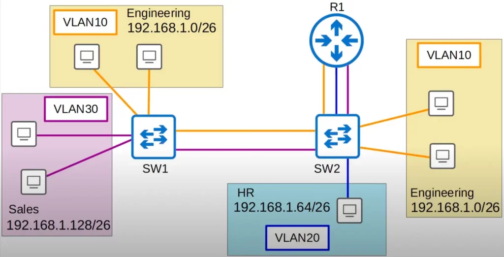
We are still using only access ports. There are two links between SW1 and SW2, one for VLAN10, and one for VLAN30. The link in VLAN10 between the two switches is necessary because VLAN10 PCs are connected to both SW1 and SW2, and also because the PCs connected to SW1 need to be able to reach R1 via SW2. The link in VLAN30 is necessary because PCs in VLAN30 also need to be able to reach R1 via SW2.
There is no link in VLAN20 between SW1 and SW2 since there are no PCs in VLAN20 connected to SW1. If PCs in VLAN20 want to reach PCs connected to SW1, R1 can perform the inter-VLAN routing.
Let’s demonstrate inter-VLAN routing.
Let’s say the PC in VLAN20 wants to send traffic to one of the VLAN10 PCs directly connected to SW1. The PC will send the frame with a destination MAC address of R1, its default gateway. R1 then forwards traffic back to SW2. Note, R1 forwards the traffic to SW2 via the VLAN10 link. The traffic arrives at SW2 on the VLAN10 interface, the traffic is now in VLAN10. So R1 forwards the traffic to SW1 on the VLAN10 connection between them, and then SW1 forwards the traffic to the destination PC.
In a small network with few VLANs, it is possible to use a separate interface for each VLAN when connecting switches to switches, end hosts to switches, and switches to routers.
However, as the number of VLANs increases, this becomes impractical and inefficient. This is because it would require a large number of interfaces, which can be expensive and difficult to manage. Additionally, routers may not have enough interfaces to support all of the VLANs.
There are two main ways to connect multiple VLANs with a single interface:
- Trunking: trunking allows a single interface to carry traffic from multiple VLANs. This is done by tagging the traffic with a VLAN ID, which identifies the VLAN that the traffic belongs to.
- Virtual interfaces: virtual interfaces, also known as subinterfaces, allow a single physical interface to be divided into multiple logical interfaces. Each logical interface can be assigned to a different VLAN.
Both trunking and virtual interfaces are effective ways to connect multiple VLANs with a single interface. The best method to use depends on the specific network requirements.
Here are some additional benefits of using trunking or virtual interfaces:
- They can save space on the switch, as you don’t need to use a separate interface for each VLAN.
- They can simplify management, as you only need to configure a single interface instead of multiple interfaces.
- They can improve performance, as traffic from multiple VLANs can be carried over a single interface.
Let’s look at how trunk ports work.
Let’s replace the separate connections for each VLAN with single connections between SW1 and SW2, and between SW2 and R1. These single connections are trunk links.
A trunk link is a physical link between two switches or between a switch and a router. It allows the transmission of traffic from multiple VLANs over a single link.
The colors of single connections are retained just for clarity, so we can see which VLANs are allowed on each trunk. But these are single physical connections.
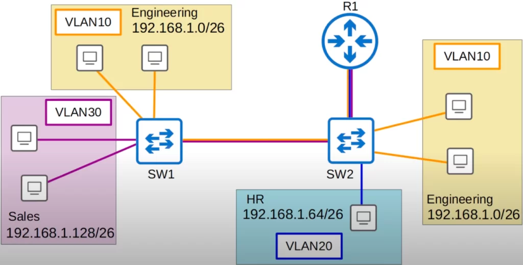
Let’s say a PC directly connected to SW2 in VLAN10 wants to send some data to another PC in VLAN 10 directly connected to SW1 (see above diagram). The PC sends the traffic to SW2, which then sends it to SW1. R1 is not involved because this is happening within the same VLAN, VLAN10.
VLAN tagging (ISL, 802.1Q)
SW1 knows which VLAN the traffic belongs to through VLAN tagging. Switches will tag all frames that they send over a trunk link. This allows the receiving switch to know which VLAN the frame belongs to. Another name for a trunk port is a tagged port, and another name for an access port is an untagged port. Frames sent over access ports are not tagged – they do not need to be tagged because the interface belongs to a single VLAN.
802.1Q encapsulation is an additional tag added to an Ethernet frame which is used to identify which VLAN traffic the frame belongs to on a trunk.
Trunk links are configured with a trunking protocol. There are 2 main trunking protocols, ISL (Inter-Switch Link) and IEEE 802.1Q (dot1q). These protocols allow the switches to identify the VLANs that are being carried on the trunk link. When a frame is transmitted on a trunk link, it is tagged with the VLAN ID of the VLAN that it belongs to. This allows the switches to determine which VLAN the frame should be forwarded to.
ISL is an old Cisco proprietary protocol that precedes the industry standard IEEE 802.1Q. Modern Cisco equipment do not support the ISL standard. For the CCNA, you only need to know about IEEE 802.1Q
IEEE 802.1Q inserts a 4-byte (32-bit) field between two fields of the Ethernet header – the source MAC address field and the type or length field.

The 802.1Q tag consists of two main fields. Those are the Tag Protocol Identifier (TPID) and the Tag Control Information (TCI). The TCI itself consists of three subfields.
Let’s look at each field of the dot1q tag. Here is a diagram of the dot1q tag format, courtesy of Wikipedia.
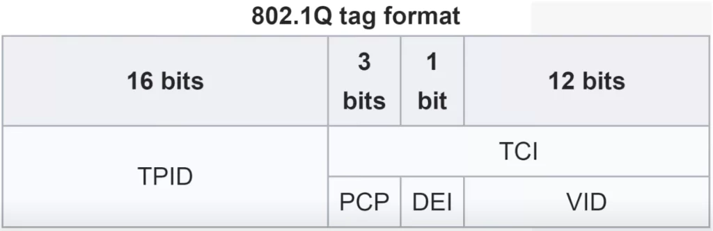
The TPID field is 16 bits or 2 bytes in length. The TPID field is always set to a value of 0x8100. “0x” just means hexadecimal. Each hexadecimal digit is 4 bits, so 4 x 4 is 16, the total length of the field. This value 8100 indicates that the frame is dot1q-tagged. When the switch sees this value of 8100, it knows the frame is dot1q-tagged.
The TCI field consists of three subfields, the PCP, DEI, and VID. The first (sub)field of the TCI is the PCP or Priority Code Point. PCP is 3 bits in length. Its use is defined by IEEE 802.1p. It is used for Class of Service, CoS, which prioritizes important traffic in congested networks. The DEI or Drop Eligible Indicator field is a single bit in length. It is used to indicate frames that can be dropped if the network is congested, which makes sure more important network traffic gets through.
The VID or VLAN ID field is 12 bits in length. This is the field that actually identifies the VLAN the frame belongs to, so you could say that this is the most important field of the dot1q tag. Because this field is 12 bits in length, that means there are 4096 total VLANs (2^12), a range of 0-4095. However, the first and last VLANs, 0 and 4095, are reserved and cannot be used. Therefore, the actual range of VLANs that can be used is 1 to 4094.
Try to remember the names of each section of the dot1q tag and their basic function for the CCNA.
Cisco’s proprietary ISL, an alternative protocol for VLAN tagging over trunk connections, also uses a VLAN range of 1 to 4094. However, ISL has almost been completely replaced by the industry standard dot1q.
The range of VLANs, which is 1 to 4094, is divided into two sections: “normal VLANs” which are numbered from 1 to 1005, and “extended VLANs” which are numbered from 1006 to 4094. Some older switches might not support the extended VLAN range, however it’s safe to expect that modern switches will support the extended VLAN range/the entire range, from 1 to 4094.
Traffic over trunk ports
Let’s look at this diagram again.
A PC in VLAN10 directly connected to SW2 wants to send traffic to another PC in VLAN10 directly connected to SW1. The traffic goes to SW2, which then forwards it to SW1 with a tag indicating that the traffic belongs to VLAN10. SW1 receives the frame, and because the destination is also in VLAN10 it will forward the traffic to the destination.
Native VLANs
IEEE 802.1Q has a feature called the native VLAN. Cisco’s ISL does not have this feature. The native VLAN is the VLAN that is used for untagged traffic on a trunk port. Traffic that is sent on a trunk port without a VLAN tag is placed in the native VLAN.
The native VLAN is VLAN 1 by default on all trunk ports. However, the native VLAN can be manually configured on each trunk port. The native VLAN must be configured on each trunk port separately, as it is not a global configuration on the switch.
The switch does not add an 802.1Q tag to frames in the native VLAN: the switch will forward a frame normally, without adding the dot1q tag to it. When a switch receives an untagged frame on a trunk port, it assumes the frame belongs to the native VLAN. So it’s important that the native VLAN matches between switches. Switches may still forward traffic if there is a native VLAN mismatch, but problems may occur.
Let’s look at an example.
A PC in VLAN10 directly connected to SW2 wants to send traffic to another PC in VLAN10 directly connected to SW1.
Let’s say we configured the native VLAN to be VLAN10 on the trunk link between SW1 and SW2. Let’s follow some traffic on the same path as before.
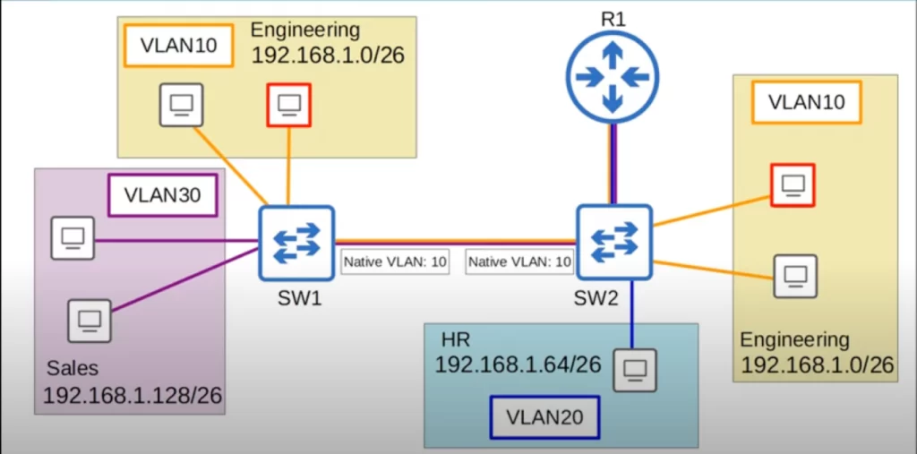
The PC sends some traffic to SW2, which will send the traffic to SW1. Because the traffic is in the native VLAN, VLAN10, SW2 will not tag it as being in VLAN10. The untagged frame arrives at SW1, which assumes that the traffic belongs to VLAN10, so it forwards it to the destination.
This time, let’s consider a scenario where there is a native VLAN mismatch configuration.
On SW2’s interface we configured VLAN10 as the native VLAN. However, on SW1’s interface we configured VLAN30 as the native VLAN. Let’s see what happens.
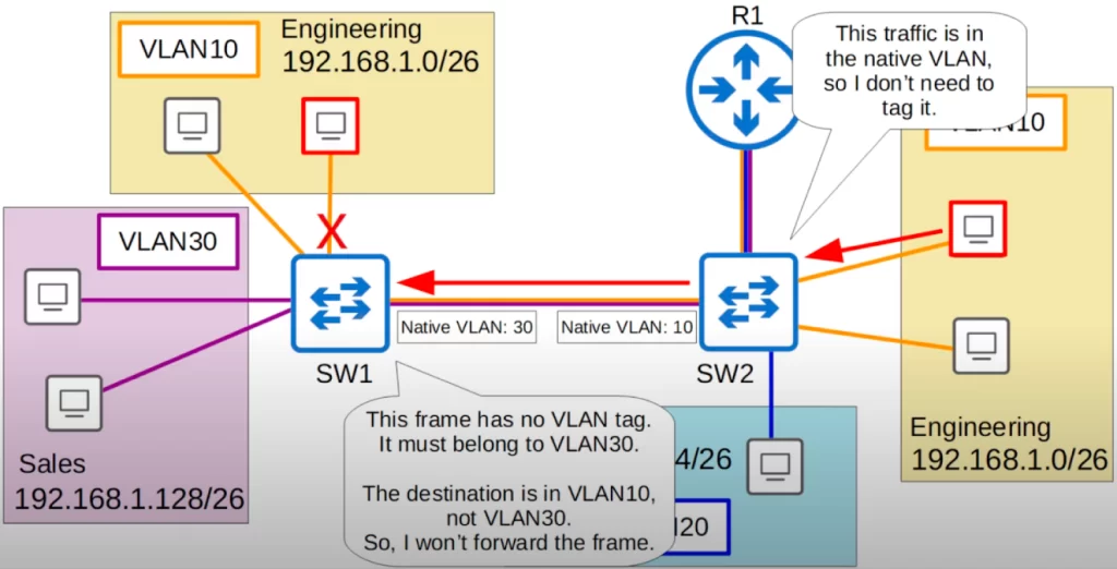
Up to the point the traffic reaches SW1, traffic flow is the same. However, when SW1 receives the frame, SW1 will think: “This frame has no VLAN tag. Therefore, it must belong to VLAN30. But, the destination is in VLAN10, not VLAN30. So, I will not forward the frame.”
Configuring trunk ports on Cisco switches
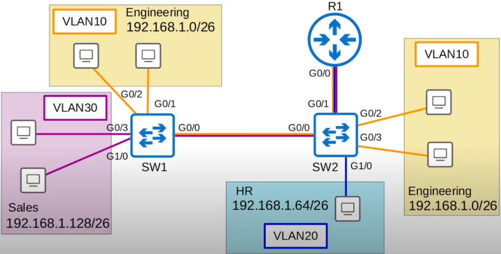
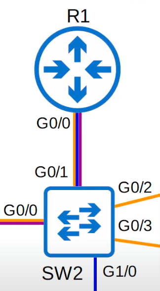
Let’s get into the configuration of trunk ports. Here is our network topology. We will be configuring G0/0 on SW1, and G0/0 and G0/1 on SW2 as trunk ports.
Let’s go on SW1 first.
First let’s look at the most basic trunk configuration, manually configuring the interface as a trunk.
From global configuration mode, enter interface configuration mode. Then use the switchport mode trunk command to manually configure the interface as a trunk port.
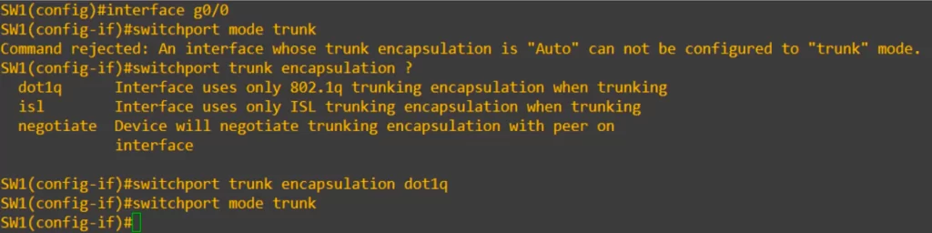
Oops, we got an error message, “Command rejected: An interface whose trunk encapsulation is ‘Auto’ can not be configured to ‘trunk’ mode”.
Switches that support both dot1q and ISL (the one used in this example) have a trunk encapsulation of “Auto” by default. To manually configure the interface as a trunk port, we must first set the encapsulation to 802.1Q or ISL. On switches that only support dot1q, this is not necessary, and we will only need the switchport mode trunk command.
After we set the encapsulation type, we can then configure the interface as a trunk.
So let’s see how to set the encapsulation type. We use the switchport trunk encapsulation command. Using the question mark lets us see the configuration options. As you can see in the CLI display, the options are dot1q, isl, and negotiate. Negotiate sets it to Auto mode, so we cannot choose that. We will revisit Auto mode in a future lesson.
Let’s set the encapsulation to dot1q, and this time the switchport mode trunk is accepted.
We use the show interfaces trunk command to confirm.
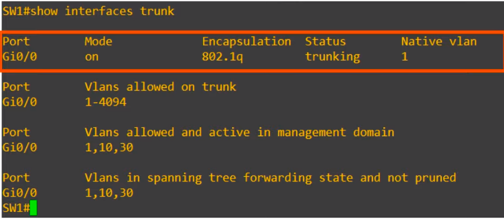
First up, the trunk interfaces are listed. “Mode on” means the interface was manually configured as a trunk. Dynamic Trunking Protocol (DTP) allows two switches to negotiate and establish a trunk link automatically. Encapsulation is dot1q as we configured, Status is trunking, and the Native vlan is the default of 1.
Under that, VLANs allowed on the trunk are displayed. By default, all VLANs, 1 to 4094, are allowed on the trunk. But for security purposes, we might want to limit which VLANs can be forwarded on the trunk. We will look at that configuration next.
Next up is VLANs allowed and active in management domain. These include the default VLAN of 1, as well as VLANs 10 and 30, which are already configured on this switch.
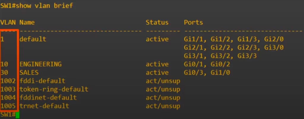
Notice, VLANs 1002 to 1005, which were discussed in VLANs Part 1, do not appear in the show interfaces trunk command output. VLANs 1002 to 1005 are not really used in modern networks.
Modifying allowed VLANs (add, remove, all, except, none)
Let’s see how to configure which VLANs can be forwarded on the trunk. Here is the command to configure the VLANs allowed on a trunk: switchport trunk allowed vlan. We have some options. Let’s go through them in this order: WORD, add, remove, all, except, and none.
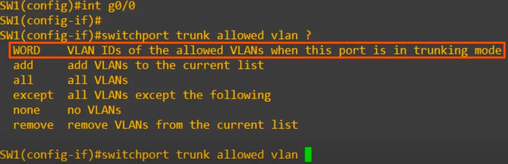
>“WORD” allows us to configure the list of VLANs allowed. Let’s see how that works.
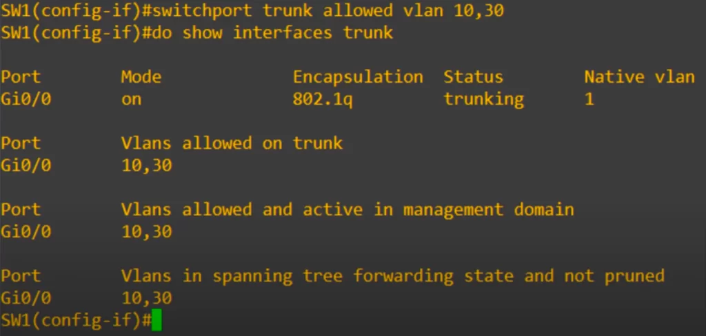
We used the command switchport trunk allowed vlan 10, 30.
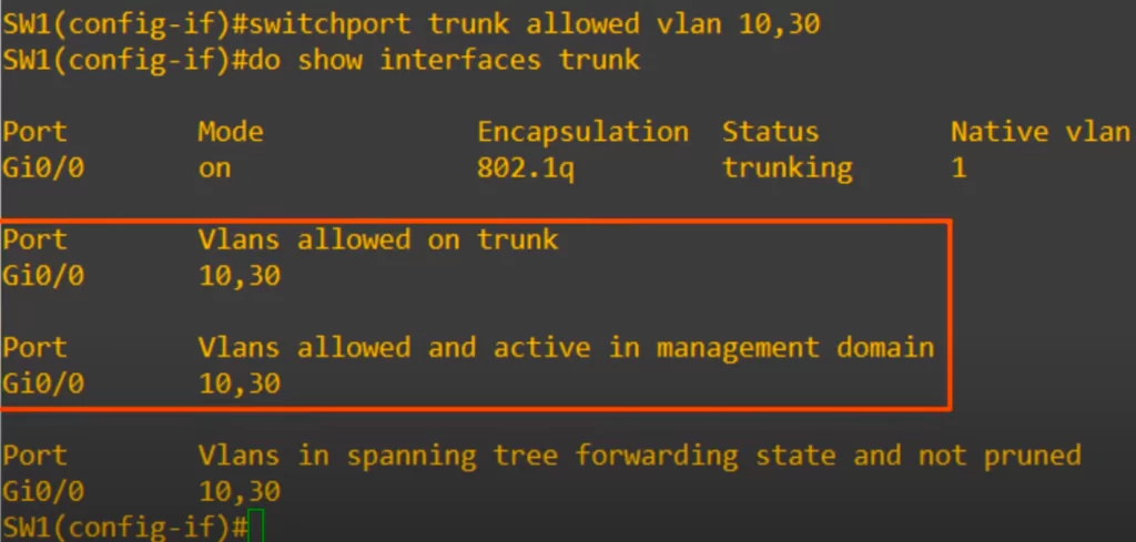
The show interfaces trunk command now only shows VLANs 10 and 30 as being allowed on the trunk.
>“add” allows us to add allowed VLANs to the currently existing list. Currently VLANs 10 and 30 are allowed.
Let’s say we also want to add VLAN20, even though no hosts in VLAN20 are connected to SW1. This time we use the command switchport trunk allowed vlan add 20.
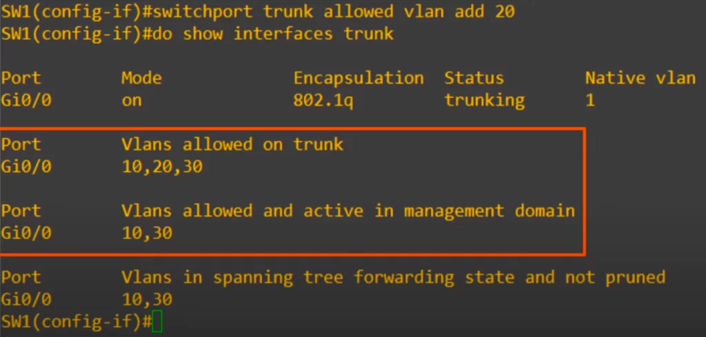
The show interfaces trunk command now shows vlans 10, 20, and 30 as allowed. So vlan 20 was added to the list.
Note that because we have not actually created VLAN20 on this switch, VLAN20 still is not displayed in the VLANs allowed and active in management domain section.
>“remove” allows us to remove a VLAN. VLAN20 is not necessary on this trunk, so let’s remove it. In interface configuration mode we use the command switchport trunk allowed vlan remove 20 and confirm with show interfaces trunk command. You should now see that VLAN20 has been removed from the list of allowed VLANs, leaving only VLANs 10 and 30.
>“all” is used to allow all VLANs on the trunk. We used the command switchport trunk allowed vlan all, and now all VLANs are allowed on the trunk.
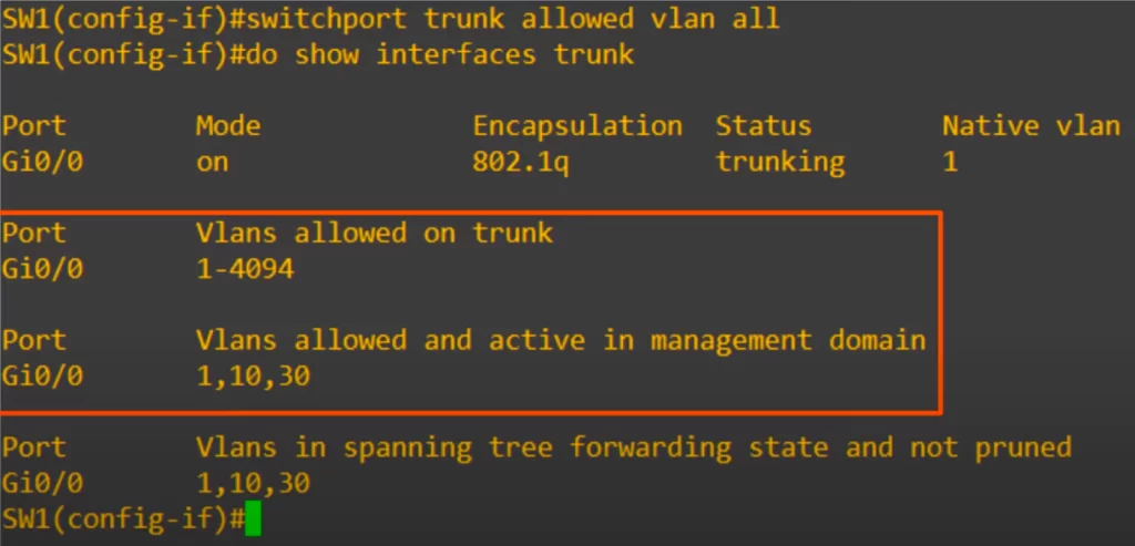
This is the same as the default state, as all VLANs are allowed by default.
>”except” is used to allow all VLANS except the VLANs we specify. We used the command switchport trunk allowed vlan except 1-5,10.
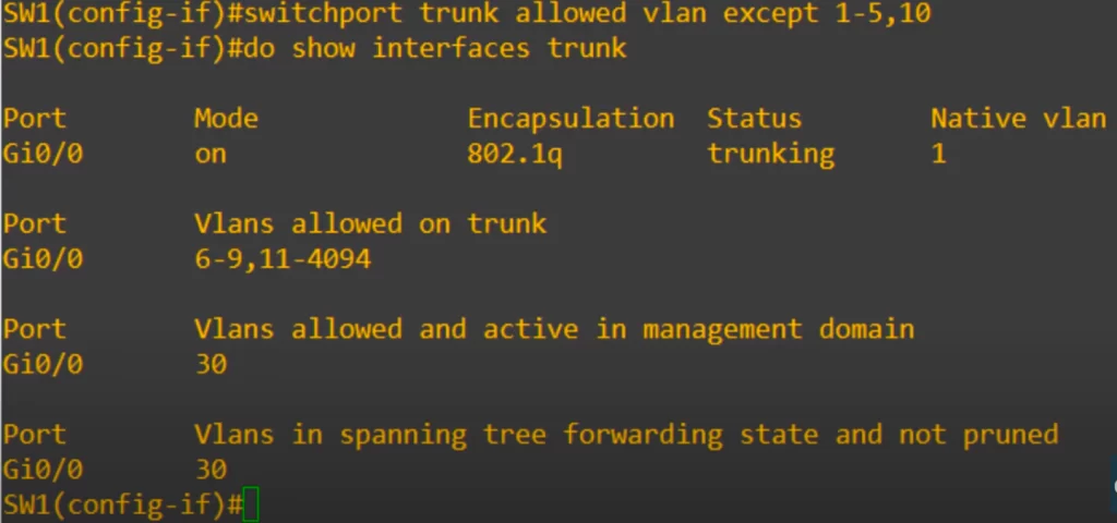
And Voila! As you can see the command allows all VLANs except those specified. So VLANs 6 to 9, and 11 to 4094 are allowed.
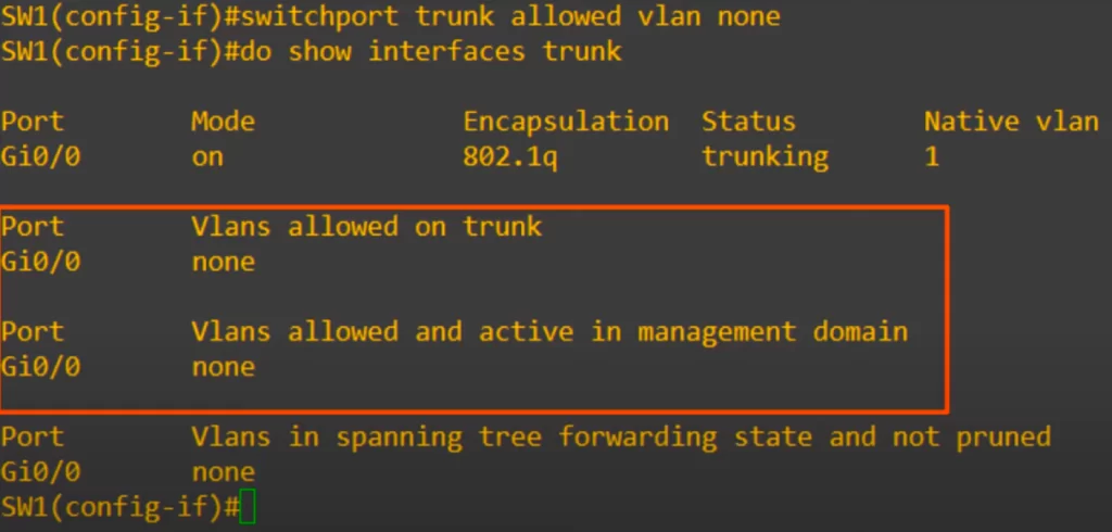
>“none” effectively allows no traffic to pass over the trunk. We used the command switchport trunk allowed vlan none. Then we checked. Now no VLANs are allowed on the trunk.
Now let’s do the actual settings we want for this network.
We are configuring G0/0 on SW1, and G0/0 and G0/1 on SW2 as trunk ports. First, we do the configurations on SW1.
SW1 has hosts in VLAN 10 and VLAN 30 connected to it. So let’s set the allowed VLANs to 10 and 30. There is no need to allow VLAN20 on the trunk link between SW1 and SW2 (there are no hosts in VLAN20 connected to SW1).
To confirm trunk ports we use the show interfaces trunk command.
Done. Now the only VLANs allowed on the trunk are VLANs 10 and 30. We limit which VLANs can be forwarded on the trunk for network security and network performance purposes.
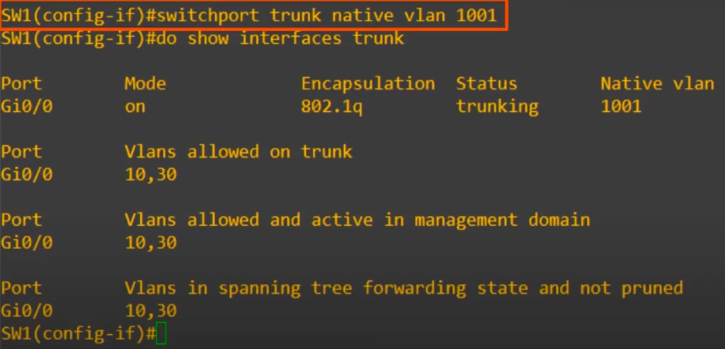
How to change the native VLAN
For security purposes, it is best to change the native VLAN to an unused VLAN. Changing the native VLAN to an unused VLAN can help to prevent VLAN hopping attacks. It can make it more difficult for unauthorized users to gain access to the network.
The command to change the native VLAN is switchport trunk native vlan, followed by the VLAN number. We chose the unused VLAN 1001. As you can see, the native VLAN has now been changed to 1001.
After configuring SW1’s G0/0 as a trunk port, we checked with show vlan brief.
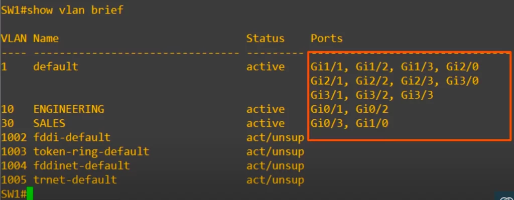
Notice that G0/0 is not listed anywhere, not in VLAN10 or VLAN30, even though those are the VLANs allowed on the trunk. This is because the show vlan brief command shows the access ports assigned to each VLAN, not the trunk ports and their allowed VLANs.
That’s it for the configurations on SW1.
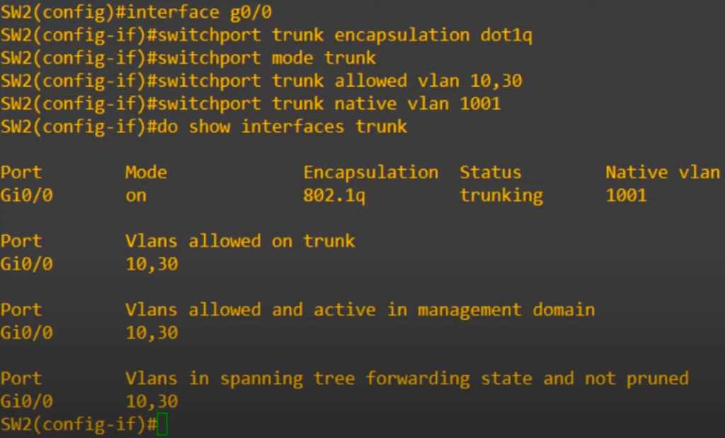
Now let’s do the configurations on SW2.
On SW2’s G0/0 interface, we must allow VLANs 10 and 30. On SW2’s G0/1 interface, however, we must allow VLAN 20 as well.
Here are the configurations for SW2’s G0/0 interface.
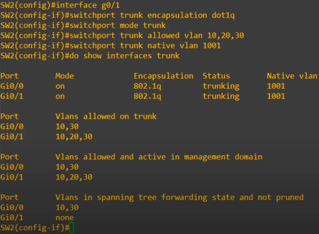
Now let’s move on to G0/1, which is connected to R1.
Here are the configurations.
That’s all for the switch configurations for this lesson.
Router on a stick (ROAS)
In VLANs study notes P. 1 we used three separate interfaces for the connection from SW2 to R1, and assigned a separate IP address to each interface on R1. Each interface IP address served as the default gateway address for the PCs in each VLAN.
See VLANs Part 1 Day 16 LAB – CCNA study notes Issue 12
Now we are going to use only one physical connection between the router and the switch. So we must use subinterfaces on R1.
Notice how the router in the network topology we have been using looks like it’s pivoted on a stick.
Router on a stick (ROAS), also known as a one-armed router, is the name used for the method of inter-VLAN routing made possible by this topology, where there is only a single physical interface connecting the router and the switch, and it looks like a stick on the network topology diagram.
In this case that one physical interface being used on R1 to connect to SW2 is G0/0. But we can divide this one physical G0/0 interface into three separate subinterfaces, which will allow us to perform inter-VLAN routing with only one physical interface.
Here is a diagram to help illustrate how this would work.
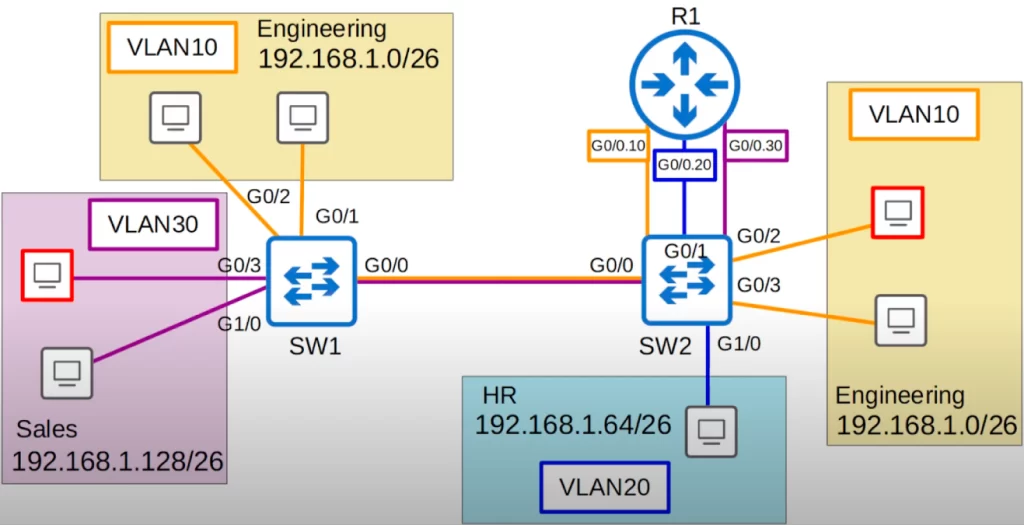
We will configure three subinterfaces on R1’s G0/0 interface, which is connected to SW2’s G0/1 interface. G0/0.10 for VLAN10, G0/0.20 for VLAN20, and G0/0.30 for VLAN30. These three logical subinterfaces are really one physical interface, R1’s G0/0.
Note that we do not need to do any additional configurations on SW2. We already configured SW2’s G0/1 as a trunk, and made sure that VLANs 10, 20, and 30 are allowed. That’s all we need to do on the switch, configure the interface like a regular trunk.
Router configurations
Now let’s look at the router configurations.
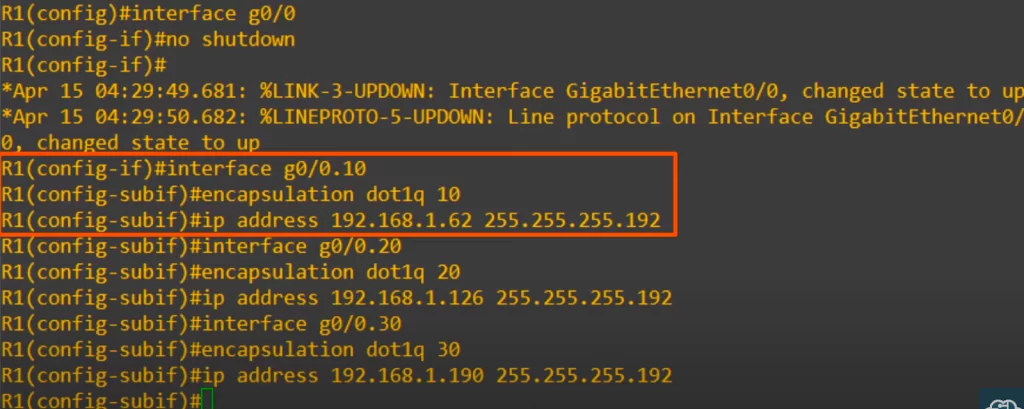
First, make sure the interface is enabled with no shutdown, as router interfaces are disabled by default.
Next up is the first subinterface. Notice how to enter subinterface configuration mode: from interface configuration mode.
R1(config-if)#interface g0/0.10
This subinterface number (dot 10) does not have to match the VLAN number (VLAN10). However, it is highly recommended that they do match, to make it easier to understand the configurations.
The next command after that is encapsulation dot1q, followed by the VLAN number, 10 in this case. This tells the router to treat any arriving frames tagged with the specified VLAN number as if they arrived on this subinterface. If a frame arrives tagged with VLAN10, R1 will behave as if it arrived on interface G0/0.10. R1 will also tag all frames leaving this subinterface with VLAN10 using dot1q.
Finally, after the encapsulation dot1q command, assign the IP address to the subinterface. We assigned the last usable address of the subnet. And that’s all for this subinterface.
We did the same thing with the other two subinterfaces. Again, we made the subinterface and VLAN numbers match, and configured the last usable IP address of each subnet as the IP address of the subinterface.
Confirm with the show ip interface brief command.
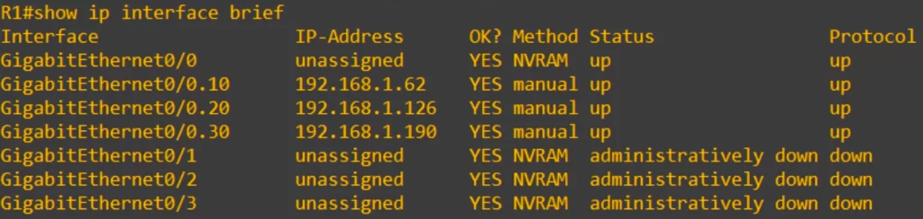
You can see that each of the subinterfaces appears, as well as the physical interface, although the physical interface itself has no IP address assigned to it.
And here is the routing table.
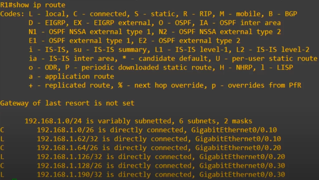
Notice the connected and local routes are added just like when IP addresses are added to regular physical interfaces. When R1 sends frames out of these subinterfaces, it adds the VLAN tag configured on the subinterface. For example, if a packet arrives destined for the 192.168.1.64/26 subnet, R1 will send the packet out of its G0/0 interface tagged with VLAN20.
ROAS review
Let’s review the important points about ROAS.
- ROAS is used to route between multiple VLANs using a single interface on the router and switch.
- The switch interface is configured as a regular trunk.
- The router interface is configured using subinterfaces. You configure the VLAN tag and IP address on each subinterface.
- The router will behave as if frames arriving with a certain VLAN tag have arrived on the subinterface configured with that VLAN tag.
- The router will tag frames sent out of each subinterface with the VLAN tag configured on the subinterface.
Now that we have configured the router, let’s return to our topology to see how inter-VLAN routing works with these subinterfaces.
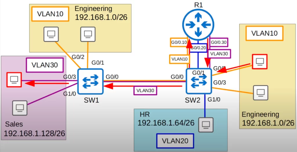
A PC in VLAN10 is trying to reach a PC in VLAN30 (follow the red arrows). The frame is sent to SW2. SW2 sends the frame on its G0/1 interface to R1, tagging it as being in VLAN10. R1 receives the frame on its G0/0 interface, identifying it as arriving on the G0/0.10 subinterface because of the VLAN10 tag. The destination is in the subnet 192.168.1.128/26, which is connected to R1’s G0/0.30 subinterface, so R1 sends the frame out of its G0/0 interface. R1 tags the frame as VLAN30 because that is what is configured on the G0/0.30 subinterface. SW2 then forwards the frame to SW1, tagging it as VLAN30 over the trunk. SW1 then forwards the frame to the destination.
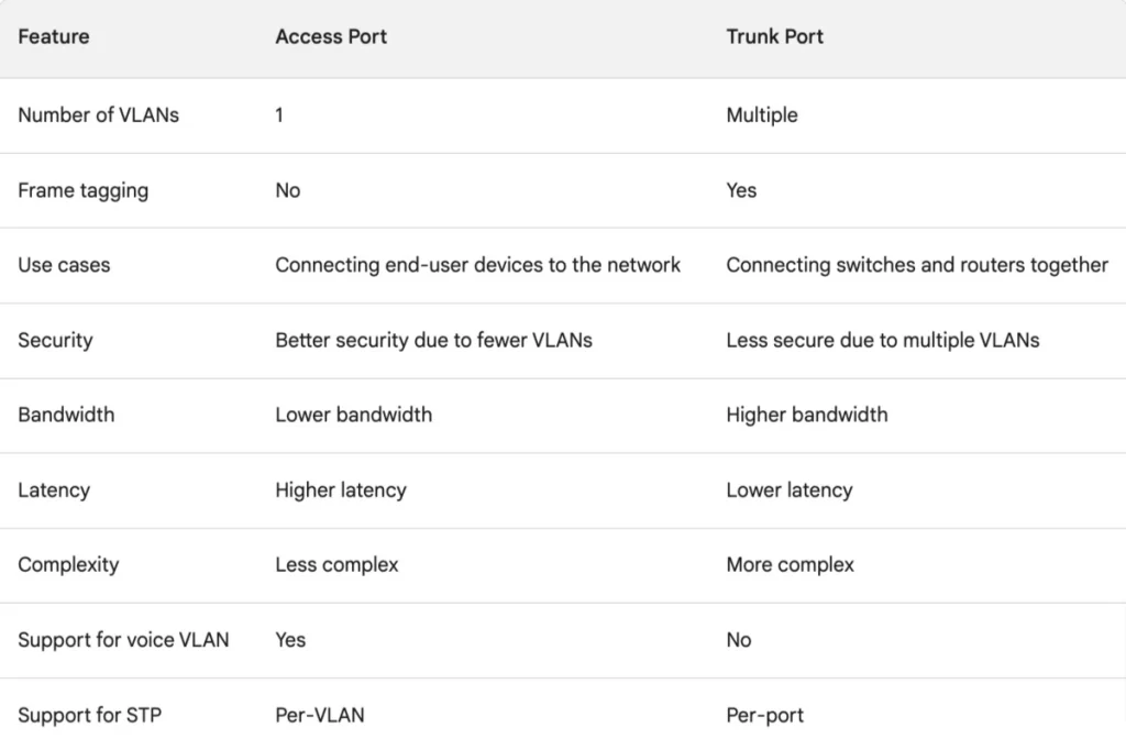
Access port vs trunk port – a brief comparison
Command review
>Manually configure the interface as a trunk:
SW(config)#interface interface
SW(config-if)#switchport trunk encapsulation dot1q
SW(config-if)#switchport mode trunk
SW#show interfaces trunk
SW(config-if)#switchport trunk allowed vlan [vlan-ids | add vlan-numbers | remove vlan-numbers | all | except vlan-numbers | none]
SW(config-if)#switchport trunk native vlan vlan-number
→to change the native VLAN to an unused VLAN (i.e., to specify the native VLAN)
>ROAS configuration:
R(config)#interface interface
R(config-if)#no shutdown
R(config-if)#interface subinterface
R(config-subif)#encapsulation dot1q vlan-number
R(config-subif)#ip address ip-address subnet-mask
→to assign an IP address to the subinterface (the last usable address of the subnet)
ROAS configuration example:
R1(config)#interface g0/0
R1(config-if)#no shutdown
R1(config-if)#interface g0/0.10
R1(config-subif)#encapsulation dot1q 10
R1(config-subif)#ip address 192.168.1.62 255.255.255.192
Free CCNA | VLANs (Part 2) | Day 17 Lab – Notes
Key learnings
*What is a trunk port? It’s a switch interface that carries traffic over multiple VLANs.
*What is the purpose of a trunk port? It allows switches to forward traffic from multiple VLANs over a single physical interface, instead of having to use a separate physical interface for every single VLAN.
*802.1Q encapsulation is a tag inserted into the Ethernet frame used to identify which VLAN the frame belongs to when sent over a trunk port.
*How to configure trunk ports on a Cisco switch, including the encapsulation type, allowed VLANs, and native VLAN.
*How to configure ROAS, which involves configuring multiple subinterfaces on a single physical interface, which allows for traffic from multiple VLANs and subnets to be routed without having to use a separate physical interface for each VLAN. It’s like a trunk port on a router.
ROAS allows routing between VLANs using one physical router interface. ROAS is a more efficient way of performing inter-VLAN routing; an alternative to using a separate router interface for every VLAN.
Key references
Note: The resources cited below (in the “Key references” section of this document) are the main source of knowledge for these study notes/this lesson, unless stated otherwise.
Free CCNA | VLANs (Part 2) | Day 17 | CCNA 200-301 Complete Course
Free CCNA | VLANs (Part 2) | Day 17 Lab | CCNA 200-301 Complete Course
Related content
Compliance frameworks and industry standards
Configuring access ports on Cisco switches
How data flow through the Internet
How to break into information security
Inter-VLAN routing using Layer 3 switches
IT career paths – everything you need to know
Job roles in IT and cybersecurity
Network security risk mitigation best practices
The GRC approach to managing cybersecurity
The penetration testing process
The Security Operations Center (SOC) career path
Back to DTI Courses


