This post discusses how switches facilitate communication within a network. It constitutes Lesson 4 of the module How data flow through the Internet. This lesson looks at everything switches do to facilitate communication within a network. Key concepts discussed in this post include the MAC address table, the four functions of switches (learning, flooding, forwarding, and filtering), unicast vs broadcast frames, and daisy chain switch typology.
- Learning objectives
- How switches facilitate communication within a network
- The MAC address table
- The four switch functions
- Unicast flooding vs broadcast
- VLANs – Virtual Local Area Networks
- Multiple switches
- Key lesson takeaways
- Key references
You may also be interested in How data flow through the Internet.
Learning objectives
- Understand how switches use the MAC address table
- Understand how switches perform their functions
- Understand how unicast flooding is different from a broadcast
- Understand what are VLANs
- Understand how switches operate when there are multiple switches involved
How switches facilitate communication within a network
Before we jump into our discussion of how switches facilitate communication within a network, a few words are in order.
Recall from Lesson 1 in this module, Network devices and their functions, switching is the process of moving data within networks. Switches are devices that perform switching.
In this lesson, we’re going to discuss everything that happens to get data from host A to host D through a switch. We will illustrate everything a switch does to enable communication between host A and host D.
For hosts to communicate with one another, they each need an IP address and a MAC address. In Lesson 3 of this module, Host to host communication in networking, we discussed how directly connected hosts communicate over the wire (Scenario 1). That discussion is germane to our present discussion.
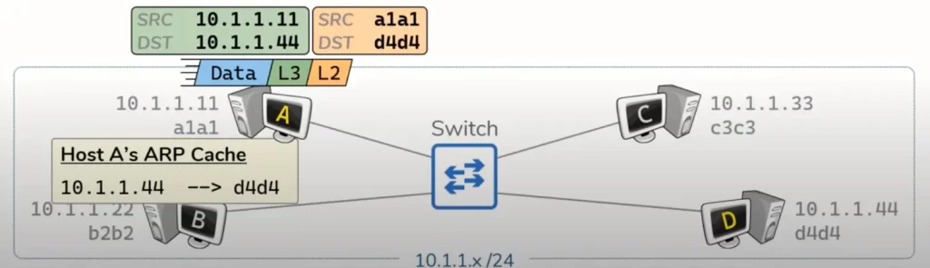
Host A will generate some data to send to host D and then add a L3 header to that data which includes the source IP address of host A and the destination IP address of host D. Then host A will perform ARP to figure out the MAC address which correlates to that destination IP address. Then host A is going to add a L2 header which indicates host A’s and host D’s MAC addresses.
Recall, switches are a L2 device – meaning they only use the L2 header to make a decision. For the switch, everything after the L2 header is just data, 0’s and 1’s.
In this lesson, we’re just going to focus on the switch – so we don’t need to consider the IP addresses that are communicating. Our starting position is that host A already knows the MAC address it is trying to speak to (normally host A would have to discover this using ARP).
The MAC address table
Switches use and maintain a MAC address table, which is a mapping of switch ports to MAC addresses. This makes it efficient to forward traffic directly to a host.
The MAC address table is where the switch stores information about the Ethernet interfaces it is connected to. The table enables the switch to forward Ethernet frames on the specific port required to reach its destination, instead of broadcasting the data on all ports (flooding the frames).
Each of the hosts in our topology are plugged into the switch in a particular port, e.g., host C is plugged into port 6.
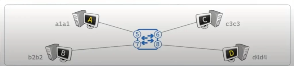
Switches can use various numbering schemes for their ports. For simplicity, we’re just going to refer to switch ports by numbers: 5, 6, 7, and 8.
A MAC address table will include the mapping of a particular switch port and the device connected to that port – meaning, it’s going to register that at port 7 exists a device with a MAC address of b2b2.
The MAC address table does not start out populated. It starts out empty. As data flow through the network, the switch will populate its MAC address table.
The four switch functions
A switch performs four actions: learn, flood, forward, and filter. If you understand these four actions, you understand how any switch for any vendor on any platform facilitates communication within a network.
Every switch regardless of the platform or vendor or code version is only ever going to perform these four actions. These are the “rules” of switching.
Let’s see how these rules work. Recall, in our example, host A wants to send data to host D.
Learning: host A is going to start putting data “encapsulated” in a L2 header on the wire. That will arrive on the switch on port 5. This will allow the switch to perform its first action, which is to learn. The switch is going to try to learn the source MAC address for every frame the switch receives.
The learning action has the switch update its MAC address table with a mapping of the switch port and the source MAC address of the received frame. Meaning, on port 5 the switch received a frame with a source MAC address of a1a1, which allows the switch to update its MAC address table indicating the device on port 5 owns the MAC address a1a1.
Flooding: now the switch will have to figure out how to transmit host A’s frame with the MAC address a1a1 to host D which has the MAC address d4d4. But at this point, looking at its MAC address table, there is no entry for the MAC address d4d4. The switch’s only option is to send copies of the frame out all ports except port 5 (the frame source). When hosts B and C receive copies of the frame, each will look at the destination MAC address. Since they are not the intended recipients of that frame, they will discard the frame. But host D will accept that frame and process it.
Filtering: when a switch needs to flood a frame, the frame will get duplicated and sent out every switch port except the switch port which received the frame (port 5 in our example).
Host D now must generate a response to host A, a frame with a L2 header with host D’s MAC address as the source and host A’s MAC address as the destination. Host D will put its response on the wire, arriving on the switch on port 8. The switch will now update its MAC address table, correlating port 8 with the source MAC address d4d4.
Forwarding: since the switch already knows that the destination MAC address a1a1 maps to port 5, the switch will forward the frame out port 5 which will allow the switch to deliver the frame directly to host A.
From here on in, anything hosts A and D need to send to each other will go directly to each other without having to do the flooding action, meaning host B and host C will not get copies of the transmission data.
Everything discussed thus far would still apply if host A was sending a packet to a router in order to speak to something else on the Internet (rather than to another host, host D in our example). The only thing that would be different would be the L3 header. The switch does not look at the L3 header to facilitate hop to hop delivery.
In our discussion thus far we illustrated how traffic flows through the switch – host A sending data to host D through the switch. Keep in mind, switches have MAC addresses. Any NIC has a MAC address. In our discussion thus far the switch’s MAC address was not involved in any communication going through the switch.
But if we were trying to send data to the switch, then the switch’s MAC address would be involved, and in that case the switch’s IP address would also be involved. If we were trying to send data to the switch, or receive data from the switch, the switch is essentially acting as a host on the local network (see Lesson 3. Host to host communication in networking).
Unicast flooding vs broadcast
We’ve discussed how host A would send a frame to host D. When host A put a frame on the wire it arrived on port 5 which allowed the switch to learn this entry in its MAC address table, and then the switch had to flood this frame because it didn’t know where the MAC address d4d4 existed.
This frame was a unicast frame. Unicast is a one-to-one communication and you can tell it is a unicast frame because the destination MAC is another host.
What if instead host A has sent a broadcast? What if host A has sent an ARP request? Recall, an ARP request is a broadcast frame, meaning it has a destination MAC address of all f’s – a specially reserved MAC address which indicates that this content needs to be delivered to everybody on the local network.
Since it is a broadcast frame the switch wouldn’t even look at its MAC address table in order to forward this frame. A broadcast frame is always going to be flooded by a switch. However, unicast frames are only sometimes flooded – specifically, if the destination MAC address is not in the MAC address table.
The terms unicast and broadcast have to do with a type of frame. Broadcast is a type of frame, specifically, a frame with a destination MAC address all f’s. While flooding is an action that a switch takes.
Insofar as traffic going through the switch, a switch will never broadcast anything. The only time a switch is going to send a broadcast is if traffic is going to or from the switch, but in this case the switch is essentially acting as another host.
VLANs – Virtual Local Area Networks
In this section we’re going to briefly introduce VLANs. VLANs allow you to divide switchboards into isolated independent groups.
VLANs allow devices that must be kept separate to share the cabling of a physical network and yet be prevented from directly interacting with one another. This managed sharing yields gains in simplicity, security, traffic management, and economy. For example, a VLAN can be used to separate traffic within a business based on individual users or groups of users or their roles (e.g. network administrators), or based on traffic characteristics (e.g. low-priority traffic prevented from impinging on the rest of the network’s functioning). (VLAN, 2022, November 21)
In the image below, switch ports are partitioned into two isolated groups, VLAN 20 and VLAN 30. A switch thus acts as multiple mini switches and each of these mini switches is going to perform each of the four switch actions independent from the other, meaning, the switch is going to maintain one MAC address table for VLAN 20 and another MAC address table for VLAN 30. And the switch will perform the four actions confined to these isolated independent groups.
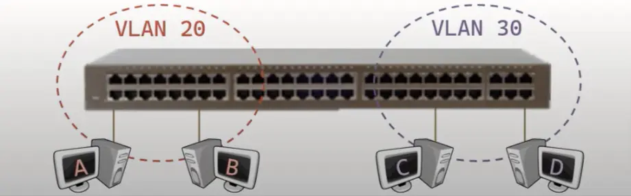
VLANs allow you to create mini switches within the big physical switch. The four switch actions still apply if you’re using VLANs – all you’re doing is confining these actions to a specific set of ports.
Multiple switches
Here, we will discuss how switches operate when there are multiple switches involved. To illustrate this we’re going to use the following topology.
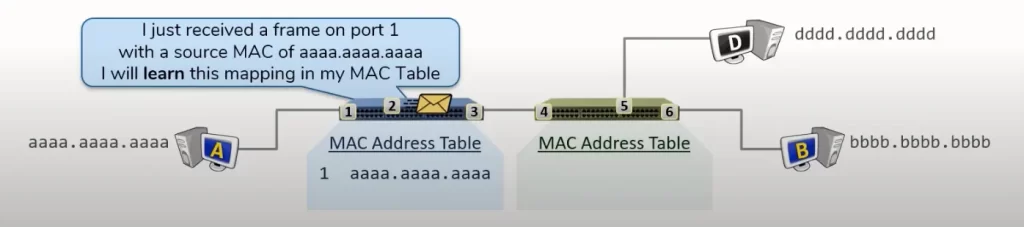
Everything we discussed so far about single switches applies if multiple switches are involved. Both the blue and green switches are going to maintain their own independent MAC address table. They will not be sharing information with each other in so far as what MAC addresses they know. Each switch will perform the four switch actions and populate their own independent MAC address table.
Let’s see how this works by going over everything that occurs for a frame to go from host A to host B and back.
Host A has some data to send to host D. This is a unicast frame, it has a destination MAC address of another host. This illustration is going to start with the assumption that host A knows the MAC address it’s trying to speak to, meaning we’re going to leave ARP out of the discussion.
When host A sends its frame out onto the wire it will arrive on the blue switch on port 1 which will allow the blue switch to learn a MAC address entry for port 1. Then the blue switch is going to look at the destination MAC address of that frame and realize it does not know where host B exists.
Therefore the blue switch is going to flood that frame out all other ports. The blue switch just did unicast flooding. Host C (concealed/not shown in the above image) will get a copy of this frame and will silently discard the frame since it is not the intended recipient (host C exists out port 2 and has the MAC address cccc.cccc.cccc).
Now from the green switch’s perspective, something just arrived on port 4 with a source MAC address of all a’s. This allows the green switch to learn a MAC address table entry for port 4. The switch is then going to look at the destination. Again the green switch does not currently know where the all b’s MAC address is, so the green switch is then going to perform the flood action and send this frame out all ports.
The green switch will flood the unicast frame. Host D will get a copy of this frame and discard it. Host B will get a copy of this frame, accept it for processing and generate a response. This response will be sent from host B’s MAC address to host A. When this response arrives on the green switch the green switch will be able to learn the MAC address which exists on port 6 which is all b’s. Then the green switch is going to look at the destination MAC address and realize that it knows how to deliver the frame and will send it out port 4. That would be the forwarding action.
The blue switch will then receive something on port 3 with a source MAC address of all b’s. This allows the blue switch to learn the switch port to MAC address mapping for port 3. Then the switch is going to look at the MAC address table to determine that this frame should be sent out port 1. The switch will forward this frame out port 1 where it will arrive on host A.
That’s what needs to happen for data to get from host A to host B and back.
As you will notice, we used the information we discussed about how data travels through a switch and showed how it applied to multiple switches.
Now it’s your turn to map out the sequence of events for a frame to go from host C to host B and the response, and also from host C to host D and the response.
Key lesson takeaways
- Switches use and maintain a MAC address table
- a mapping of a switch port to a MAC address
- Switches perform four actions – learn, flood, forward, filter
- learn: update MAC address table with mapping of switch port to MAC address
- flood: duplicate and send frame out all switch ports except receiving port
- forward: use MAC address table to deliver frame to appropriate switch port
- filter: a switch will never forward a frame back out the same port which received the frame
- broadcast is always flooded whereas unicast frames are occasionally flooded
- Traffic going through the switch vs traffic going to the switch
- switch acts as a host in the network (traffic going to the switch)
- Multiple switches
- switches maintain independent MAC address tables
- switches perform switch actions independently
Key references
Everything Switches do – Part 1 – Networking Fundamentals – Lesson 4 (PracNet, Part 1)
Everything Switches do – Part 2 – Networking Fundamentals – Lesson 4 (PracNet, Part 2)
Related content
Compliance frameworks and industry standards
How to break into information security
IT career paths – everything you need to know
Job roles in IT and cybersecurity
Network security risk mitigation best practices
The GRC approach to managing cybersecurity
The penetration testing process
The Security Operations Center (SOC) career path
Back to DTI Courses


