This post discusses how routers facilitate communication between networks. It constitutes Lesson 5 of the module How data flow through the Internet. This lesson looks at everything routers do to facilitate communication between networks. Key concepts discussed in this post include the difference between a router and a host, the routing table, the ARP table, and hierarchical network topology.
- Learning objectives
- How routers facilitate communication between networks
- Routers have an IP and a MAC for each network they interface with
- The difference between a router and a host
- Routers use and maintain a routing table
- Methods a routing table can be populated with routes
- Directly connected route
- Static route
- Dynamic route
- Routers use and maintain ARP tables
- Why are routers deployed in a hierarchy
- Routers in a hierarchy are easier to scale
- Routers in a hierarchy provide a more consistent connectivity
- Route summarization
- Key lesson takeaways
- Key references
You may also be interested in How data flow through the Internet.
Learning objectives
- Understand the difference between a router and a host
- Understand how a routing table can be populated with routes
- Understand how routers use their routing tables and ARP tables to move packets across the Internet
- Understand why you would want to deploy your routers in a hierarchy
How routers facilitate communication between networks
Before we jump into a discussion of how routers facilitate communication between networks, please review the first four lessons in this module (listed here: How data flow through the Internet) as they contain necessary background for our present discussion.
In this lesson we will discuss everything routers do to move data across the Internet. This lesson will explain the process that every router will follow and how routers will use their routing and ARP tables to move packets across the Internet.
We will go over every step that occurs for a packet to get from host A to host C and for host C to respond sending the packet back to host A (see Figure 1). This lesson will explain the steps for how a packet gets from host A all the way through to host C whether host C is on the other side of two routers or six routers or the other side of the Internet.
Normally for two hosts to speak to each other within a network they would have to be connected to a switch and this switch will facilitate all the communication within this network. To keep things simple we’re going to leave switches out of this lesson entirely, but everything previously discussed about how switches facilitate communication within a network in Lesson 4 still applies, so feel free to review Lesson 4.
Routers have an IP and a MAC for each network they interface with
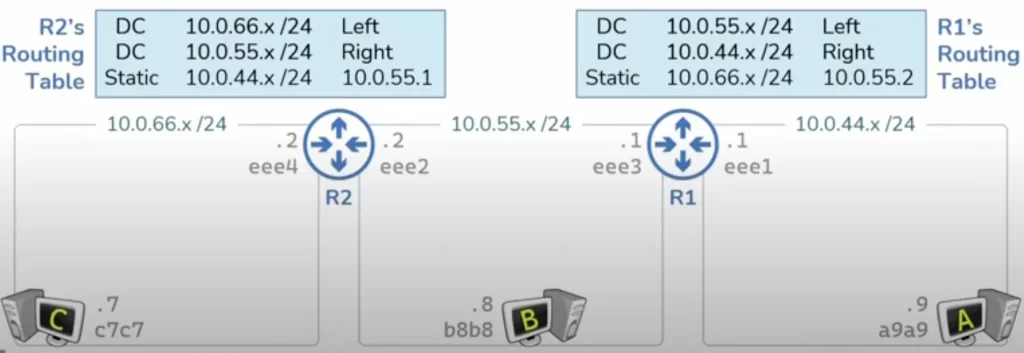
Here is a network topology (see Figure 1) with three hosts (A, B, and C), two routers (R1 and R2), and three networks. Each host has a MAC address and is configured with an IP address in its respective network’s IP address space. Each router has a MAC address and an IP address for each network interface a router is connected to.
Here we’ve configured R1 with the IP address 10.0.55.1 and that is what connects R1 to the IP network 10.0.55.x.
The difference between a router and a host
But if both routers and hosts have an IP address and a MAC address, what then is “the real difference” between a router and a host?
We can get a “definitive” definition of a router from the RFC 2460 IPv6 specification – it provides a useful definition for hosts and routers that also applies to IPv4. The RFC defines a node as anything which implements IP or anything with an IP address. It then defines a router as any node that forwards packets not addressed to itself, which leaves the definition of a host to be a node that is not a router.
So the real difference between a router and a host is that routers forward packets not destined to themselves.
Routers use and maintain a routing table
For routers to forward packets, they must maintain a map of all networks they know about. This map is known as the routing table. Inside a routing table is what’s known as routes and each route is merely a set of instructions for how to reach a specific network.
A routing table is a mapping of an IP network to an interface or an IP network to an IP address of the next router in the path (the next hop IP address).
For our topology in Figure 1, R1 is going to have routes correlating to each of the two networks 10.0.55.x and 10.0.44.x. The first route will tell R1 that to reach anything in the 10.0.55.x network R1 should send that packet out the left interface and the second route will tell R1 that to reach anything in the 10.0.44.x network R1 should use its right interface (router interfaces typically have more technical names, such as Fa0/1 or eth0 or E3).
The routing table is a very important concept in networking. A large part of a network engineer’s job is to ensure that every router has the proper routes in its routing table in order to move packets through a network.
Methods a routing table can be populated with routes
Follows are three ways that routes can be populated in a routing table (refer to Figure 1).
Directly connected route
The first method is what’s known as directly connected. A directly connected route exists for every network that a router is directly attached to.
R1 is directly connected to two different networks and therefore will have two different directly connected routes in its routing table – the first one telling R1 that the 10.0.55.x network exists out the left interface and the second one telling R1 that the 10.0.44.x network exists out the right interface.
R2 sits in between the 10.0.55.x network and the 10.0.66.x network. Each router is going to maintain its own routing table that is independent from the other. In each case the routing table is a map of every network that a router knows about.
To attach R1 to the 10.0.44.x and the 10.0.55.x networks we have to configure an IP address in each of those networks. Ditto for R2 to be attached to the 10.0.55.x network we’re going to have to plug R2 in and then configure an IP address in this network. In this case we’ve configured the IP address 10.0.55.2. This created a directly connected route in R2’s routing table telling R2 that the 10.0.55.x network exists out R2’s right interface. As soon as we configure the IP address 10.0.66.2 on R2’s left interface this adds a new directly connected route to R2’s routing table telling R2 that the 10.0.66.x network exists out R2’s left interface.
Each of these routers will now use their own routing table to move packets through this topology. For example, if host C sent R2 a packet with a destination IP address of 10.0.55.8 (host B’s IP address), R2 will take a look at its routing table to determine that the 10.0.55.x network exists out the right interface and will forward that packet along.
But what happens if host C sent R2 a packet with a destination address 10.0.44.9 (host A’s IP address)? When R2 takes a look at its routing table it’s not going to find an entry for the 10.0.44.x network. At this point R2 does not know how to get to the 10.044.x network, which means R2 is going to drop that packet. When a router receives a packet with a destination IP address it does not know how to get to the packet is going to be dropped.
Remember from the perspective of each router, the routing table is a map of every network that exists. And at this point R2 does not know that the 10.0.44.x network exists. And since R2 is not directly attached to the 10.0.44.x network it’s not going to have a directly connected route in order to get to the 10.0.44.x network.
But there are two other methods for how a routing table can be populated with routes.
Static route
The second method to populate a routing table is what’s known as a static route. A static route exists anytime an administrator manually provides instructions to a router about the location of a particular network. For example, I can log into R2 and configure it with a static route telling R2 that anytime it wants to reach the 10.0.44.x network it should send that packet to the 10.0.55.1 IP address which is R1’s IP address.
If R2 received a packet with a destination IP address of 10.0.44.9 from host C it will take a look at the destination IP address, find a match in its routing table, and forward that packet along to the next router in the path, in this case R1. R1 will then look at its routing table and determine that the packet should be sent out the right interface where it will arrive on host A.
But what happens if host A responds? This response is going to have a destination IP address of 10.0.66.7 which is host C’s IP address. When R1 receives this response it’s going to take a look at its routing table and at the moment R1 does not know how to deliver this packet. So normally R1 would just drop this packet. But just like we used a static route to tell R2 about the 10.0.44.x network we can also use a static route to tell R1 about the 10.0.66.x network.
This static route would tell R1 that the 10.0.66.x network can be reached by going to the 10.0.55.2 IP address which is R2’s IP address. With this static route, R1 now has instructions on what to do with that packet which is to send it to R2. R2 will then look at its routing table to determine that the 10.0.66.x network is out the left interface where it will deliver the packet to host C. Thus we used static routes to tell both of these routers about the networks that they did not know about because they were not directly attached to them.
Dynamic route
The third way that a routing table can be populated is known as dynamic route. A dynamic route is very similar to a static route except instead of an administrator telling the router how to get to a particular network a dynamic route has the routers automatically talking to each other and sharing information that they know in order to tell each other how to get to the networks that they can get to.
For example, if we told R1 and R2 to do dynamic routing among each other, R1 would share with R2 that R1 knows about the 10.0.55.x and the 10.0.44.x networks. R2 would say I already know about the 10.0.55.x network but I do not know about the 10.0.44.x network. Anything R2 gets destined to the 10.0.44.x network is going to send to R1. In the same way R2 will tell R1 that it knows about the 10.0.66.x and 10.0.55.x networks and R1 will learn that anything destined to the 10.0.66.x network should be sent to R2.
Routers will talk to each other to share dynamic routes using different dynamic routing protocols – they include RIP, OSPF, BGP, EIGRP, IS-IS. Each of these protocols differs insofar as how often networks are shared with one another, how they discover each other’s presence, what sort of information is included with each route, and how much control you have over the routes that are received or sent.
Routers use and maintain ARP tables
Everything with an IP address has an ARP table. Since routers have IP addresses therefore they also have ARP tables. Recall, ARP is a mapping of a L3 address like an IP address to a L2 address like a MAC address. In each case the routers’ ARP tables are going to maintain a mapping of IP addresses to MAC addresses of all the nodes in directly connected networks.
Unlike routing tables, ARP tables start out empty. An ARP table will get populated dynamically as needed as traffic is flowing through the network. The routing table has to be populated ahead of time. Recall that if a router receives a packet that it does not know how to deliver the router is going to drop that packet. But with ARP if the router does not have an ARP entry it needs it can do the address resolution process to figure out what it needs.
Take a look at R1’s ARP table (Figure 2). We’re going to study how R1 and R2 use their routing tables and ARP tables in order to get a packet all the way from host A through both of these routers to host C.
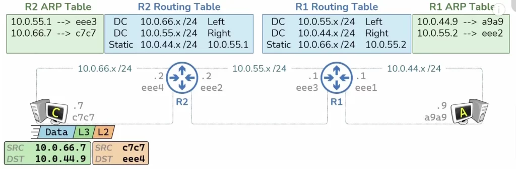
To start, host A has some data it needs to send to host C. Host A knows the IP address it’s trying to speak to, so it’s able to construct a L3 header that’s going to include a source IP address of host A (10.0.44.9) and a destination IP address of host C (10.0.66.7).
Host A can look at the destination IP address and compare that to its own IP address and subnet mask to determine that what it’s trying to speak to is on a foreign network, which means this packet must be sent to host A’s default gateway which in this case is R1. If this is the first packet that host A will send, host A does not know R1’s MAC address and therefore cannot construct the necessary L2 header which would take this packet from host A’s NIC to R1’s NIC.
So before host A can send the packet, host A is going to have to perform ARP.
Host A will send an ARP request to the IP address of R1 (10.0.44.1). The ARP request is going to ask for the MAC address for whoever owns the IP 10.0.44.1. Notice in the ARP request host A is going to include its own IP to MAC address mapping. This ARP request will be sent across the wire where it will be received by R1. When R1 receives the ARP request, R1 will be able to learn the ARP mapping of the sender of the ARP request. R1 will add that ARP entry to its ARP table upon receiving the ARP request.
Now R1 needs to generate a response. That response will include the ARP mapping that host A was trying to resolve. When that ARP response gets back to host A, host A will populate its ARP entry with the MAC address of its default gateway and now host A has everything it needs to properly construct the L2 header which will get this packet from host A to the router, R1.
Host A can now send all of this to R1. When the router receives this packet the first thing the router is going to do is discard the L2 header, as it has served its purpose. Now R1 will look at the destination IP address in its routing table. It’s going to try and find a match to determine where to send this packet next. It will see that there’s a match (static route 10.0.66.x /24) which will tell R1 that the next hop for this particular packet is the IP address 10.0.55.2 which is R2’s IP address.
Now R1 needs to construct a L2 header which will take the packet from the MAC address ee3 to the MAC address ee2. But at this point R1 does not have an ARP entry for the IP address 10.055.2, therefore R1 cannot construct the L2 header as necessary which means R1 is going to have to perform ARP.
R1 will send an ARP request to the IP address 10.0.55.2. Just like before, the ARP request includes the sender’s ARP mapping. This is going to allow R2 to learn the ARP mapping of the sender of that ARP request.
Upon receiving the ARP request R2 will learn that something with the IP address 10.0.55.1 has the MAC address ee3. Now R2 will generate an ARP response, i.e., the ARP mapping that R1 was trying to discover. When R1 receives this ARP response R1 will be able to complete its ARP entry and therefore create a L2 header which will get the packet through to the next hop. Once it gets there R2 is going to receive the packet and discard the L2 header.
Then R2 will look at the destination IP address in the routing table to try and determine what to do with that packet. It will find a match (10.0.66.x /24) indicating that this packet needs to be delivered out the left interface. Since R2 is now delivering this packet through a directly connected route it knows that this is the final hop for this particular packet because the destination exists in a directly connected network. So R2 will need to construct a L2 header which will take the packet from R2’s NIC to host C’s NIC.
But just like before R2 currently does not know host C’s MAC address and therefore cannot create the L2 header. R2 is going to have to send an ARP request to resolve the L2 address for host C. This will follow the same process we’ve already outlined. Host C will learn the MAC address mapping for R2 by receiving the ARP request from R2. This will be useful for the return traffic back to host A. Then host C will generate an ARP response. This ARP response is going to include the ARP mapping that R2 was trying to resolve.
Once R2 receives the ARP response it will populate its ARP table with the appropriate MAC address and then it can finally create the appropriate L2 header to get the packet to host C. When host C receives this packet it’s going to discard the L2 header – this header’s purpose was to take the packet from eee4 to c7c7. Then host C is going to discard the L3 header – the purpose of that header was to take the data from 10.0.44.9 to 10.0.66.7. And finally host C will process the data.
That is every single step that needs to happen in order to get data from host A to host C.
Next, let’s go over what needs to happen in order to get a response from host C back to host A. You will notice the way back will go faster because all of the necessary ARP entries have already been populated.
It starts with host C having some data to get to host A, so host C will create a L3 header with a source IP address of host C’s IP address and a destination appears a host A’s IP address. And since host C knows that the destination IP address is on a foreign network host C knows that this packet needs to go to its default gateway which in this case is R2.
And since host C already has the ARP mapping for R2 it can create the L2 header necessary to get the packet to the next hop (from c7c7 to eee4). Once R2 receives the packet it will discard the L2 header then look up the destination IP address in its routing table to determine what to do with the packet. R2 will find a match for the destination IP address 10.0.44.9 in its routing table (a static route telling R2 that to reach the network 10.0.44.x/24, forward traffic to the IP address 10.0.551, which is R1’s IP address). So R2 knows that the next hop for the packet is the IP address 10.0.55.1 of R1, and since R2 already has an ARP mapping for R1, R2 can instantly create the necessary L2 header to get the packet across this hop.
So with that L2 header created, R2 can now send the packet to R1. Once it arrives at R1, R1 will discard the L2 header and then look up the destination IP address in its routing table. It will find a match for this route (10.0.44.x /24 Right) which tells R1 that this particular packet needs to be delivered out the right interface to its final hop. And since R1 has the ARP mapping for the IP address 10.0.44.9, R1 is able to construct a L2 header which will get the packet across to its final hop. This will then allow R1 to send this packet to host A. Once host A receives the packet host A will discard the L2 header then host A will discard the L3 header and finally host A will process the response data.
And that is everything that occurs to get the response data from host C all the way back to host A.
Everything we did between R2 and R1 in order to move data from host C to host A would repeat for any amount of routers in the path. In each case every router in the path would look up the destination IP address in their routing table to determine the next hop IP address and then construct a L2 header with the appropriate MAC addresses to get the packet across to the next hop. If for whatever reason a router does not know the destination MAC address that router will perform ARP as necessary.
The steps we just illustrated to get a packet from R2 to R1 are the same. But those same steps would also occur if there were many other routers in the path between R2 and R1 – whether host A is on the other side of two routers or six routers or the other side of the Internet. In fact, the Internet is essentially a series of routers that are handing packets off between other routers.
Why are routers deployed in a hierarchy
In this section we will discuss why routers deployed in a hierarchy allow topologies to scale much easier, provide a more consistent connectivity experience for network users, and allow for route summarization.
Routers in a hierarchy are easier to scale
The following illustration should make it clear why a network design where routers are deployed in a hierarchy is much easier to scale.
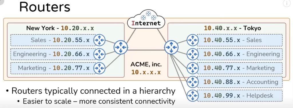
Consider the network topology in Figure 3 representing the extended IP network of the ACME corporation. Let’s say the Tokyo network decides to expand and add two more networks, the accounting network and the helpdesk network. In each case a router is stowed up to handle the traffic for each of those networks and that router is connected once into some sort of aggregation router and instantly both of these networks now have connectivity into the rest of the topology of the ACME network.
Routers in a hierarchy provide a more consistent connectivity
To argue the second point, why routers deployed in a hierarchy provide a more consistent connectivity experience for users, we will need to reconfigure these routers so that they are not deployed in a hierarchy and instead deployed linearly (see Figure 4).
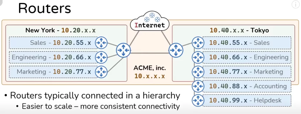
Notice in the Tokyo network, now if the sales team wants to speak to someone in the marketing team they only have to cross three routers to get there. But if the sales team needs to speak to someone on the helpdesk they now need to cross five routers to get there and this same effect happens in the reverse direction for traffic going to the Internet.
Notice, for the engineering team to speak to the Internet it only needs to cross three routers. But the accounting team needs to speak through five routers to get to the Internet. You can see that if you deploy your routers in a line as illustrated you do not have very consistent connectivity. If some sort of failure event happens at the marketing router, it can cut off access to the rest of the network for all the teams deployed after the marketing network.
You do not have those problems if your routers are deployed in a hierarchy: if something were to occur to the marketing router the accounting network and the helpdesk network are not affected. Further, for the sales team to speak to engineering, it has to cross three routers or for the sales team to speak to the helpdesk, it still has to cross only three routers. And of course in all cases for any of these teams to speak to the Internet they just have to cross two routers. This makes for a much more consistent connectivity experience for the users in your network.
These were two reasons why physically routers are typically deployed in hierarchical topologies. But there is still another reason: routers in a hierarchy allow for route summarization.
Route summarization
To explain route summarization let’s focus on R5 for a moment and let’s take a look at R5’s routing table.
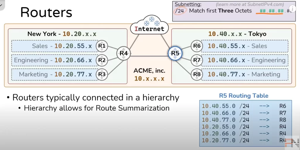
Recall, every router has a routing table and that routing table is a map of every network that exists. In this topology (Figure 5) we have six networks and R5 is going to need a route for each of them: three networks to account for the three teams in Tokyo pointing to R6, R7, and R8 respectively and three more networks accounting for the teams in New York, each pointing to R4.
The /24 you see in R5 Routing Table can be fully explained within the domain of subnetting. The present discussion, however, will only provide a brief explanation for it. This slash 24 refers to the bits in the IP address. When we say /24 we mean that the six routes in the R5 Routing Table are going to match on the first three octets of a destination IP address.
Recall from Lesson 1, IPv4 addresses are 32 bits (4 bytes) in length comprised of four 8-bit groups of numbers or 4 octets and we represent each of those octets as a decimal number – when we say slash 24 what we are saying is we’re going to match on the first 24 bits or first three octets.
If a packet showed up to R5 with a L3 header destination IP address of 10.40.77.9, R5 will look at its routing table to find a route match. Looking at R5 Routing Table, the packet will be forwarded to R8.
But notice in R5’s routing table, the three bottom routes point to R4, accounting for each of the three networks in the New York office.
But everything at the New York office starts with 10.20. So we could simplify thee three bottom routes into a single route telling R5 to only look at the first two octets to find a match on 10.20. We can do this by telling R5 to match on a slash 16 network: 10.20.0.0 /16. If a slash 24 matched on the first 24 bits then a 16 is going to match on the first 16 bits which means the first two octets.
The route 10.20.0.0 /16 tells R5 that any packet with a destination IP address that has a 10.20 in the first two octets should be sent to R4 and then R4 will hand it off to the next appropriate router in the path.
It might not seem that a jump from three routes to one route is all that useful but what if the New York office scales? Here we only have three networks but what if we added another 10 networks or 100 networks?
Since they all belong to New York they are all going to start with the 10.20 IP space and R5’s routing table will not have to change – this one route will account for any additional networks added to the New York IP space. So that’s one of the benefits of route summarization, it reduces the routes in a routing table.
Note: in the context of summarization, when a router receives a packet whose destination IP address matches more than one route in the routing table, the router will choose the most specific route to forward the packet.
Notice where R8 sits in this particular topology (Figure 5): to reach anything on the Internet R8’s next hop is always going to be R5. Since R8 needs to use R5 regardless whether it’s trying to speak to Tokyo, New York, or anything on the Internet, we can give R8 what’s known as a default route.
A default route is a kind of ultimate route summary. It looks like this: 0.0.0.0 /0. It uses a slash zero route. Just like a slash 24 match on the first three octets and a slash 16 match on the first two octets and a slash eight match on the first octet, a zero would match on zero octets which means every single IP address is matched by this particular route.
This default route is essentially telling R8 that to get to anything go to R5, which if you look at the topology that R8 is deployed within, that is indeed the next path whether it’s speaking to Tokyo, New York, or anything out on the Internet.
Key lesson takeaways
- Routers have an IP and a MAC for each network they are connected to
- Routers forward packets not destined to themselves
- Routers use and maintain a routing table – a map of all the networks they know about
- Routing tables can be populated via three methods
- directly connected routes – routes for attached networks
- static routes – routes manually provided by an administrator
- dynamic routes – routes learned automatically from other routers
- Routers use and maintain ARP tables – mapping of L3 to L2 addresses
- everything with an IP address has an ARP table
- unlike routing tables, ARP tables start out empty
- Routers are typically connected in a hierarchy
- easier to scale
- provide a more consistent connectivity
- route summarization (reduces number of routes in a routing table)
Key references
Everything Routers do – Part 1 – Networking Fundamentals – Lesson 5 (PracNet, Part 1)
Related content
Compliance frameworks and industry standards
How to break into information security
IT career paths – everything you need to know
Job roles in IT and cybersecurity
Network security risk mitigation best practices
The GRC approach to managing cybersecurity
The penetration testing process
The Security Operations Center (SOC) career path
Back to DTI Courses


