This is the third and final installment of my study notes on the topic of OSPF for the CCNA. We begin with some notes on loopback interfaces. Configuring a loopback interface on a router provides an interface with an IP address that is always up and can consistently be used to identify and reach the router. Then we discuss OSPF network types, focusing on the broadcast network type and the point-to-point network type. We discuss the role and election of designated routers and backup designated routers in a subnet and we configure the OSPF interface priority on a router in an OSPF broadcast network. A brief discussion of the characteristics and configuration of serial connections is offered because the topic comes up when discussing the point-to-point network type. We configure the clock rate on the DCE side of a serial connection, and we configure PPP encapsulation on a point-to-point router. Then we learn how to manually configure the OSPF network type of an interface on a router. Then we study OSPF neighbor/adjacency requirements from the perspective of troubleshooting potential problems that can prevent routers from successfully forming OSPF adjacencies. Finally, we look at the three most basic LSA types: Type 1 (Router LSA), Type 2 (Network LSA), and Type 5 (AS external LSA) – their roles in communicating the router’s local routing topology to all other local routers in the same OSPF area.
OSPF Part 2, How routers become OSPF neighbors, covers the seven OSPF neighbor states, three methods to change the OSPF cost, how to configure OSPF directly on a router interface, and how to configure passive OSPF interfaces.
OSPF Part 1, Basic OSPF operations, covers foundational concepts related to the operations of OSPF, in addition to covering basic OSPF configurations, including how to configure OSPF on a router, how to configure a passive interface on a router, how to advertise a default route into OSPF, and how to manually configured a router ID on a router. This post constitutes Issue 23 of my CCNA 200-301 study notes.
- Loopback interfaces
- OSPF network types
- OSPF broadcast network type
- Broadcast – DR/BDR election
- Broadcast – OSPF priority
- OSPF point-to-point network type
- Serial interfaces
- Serial interfaces summary
- Configuring the OSPF network type
- Broadcast vs point-to-point chart
- OSPF neighbor/adjacency requirements
- OSPF LSA types
- Command review
- Key learnings
- Practice quiz questions
- Key references
You may also be interested in CCNA 200-301 study notes.
Loopback interfaces
*A loopback interface is a virtual interface in the router. The virtual interface is always up/up (unless you manually shut it down). This means that the status of a loopback interface is not dependent on a physical interface. Physical interfaces can have hardware problems and fail, however that cannot happen to a loopback interface unless the router itself fails.
*A loopback interface provides a consistent IP address that can be used to reach and identify the router. Sometimes you need to send traffic directly to a router. Let’s say R1 has no loopback interface, and R4 receives a packet destined for R1 at 10.0.13.1, the IP address of R1’s G1/0 interface. R4 might forward the packet to R1 like this:
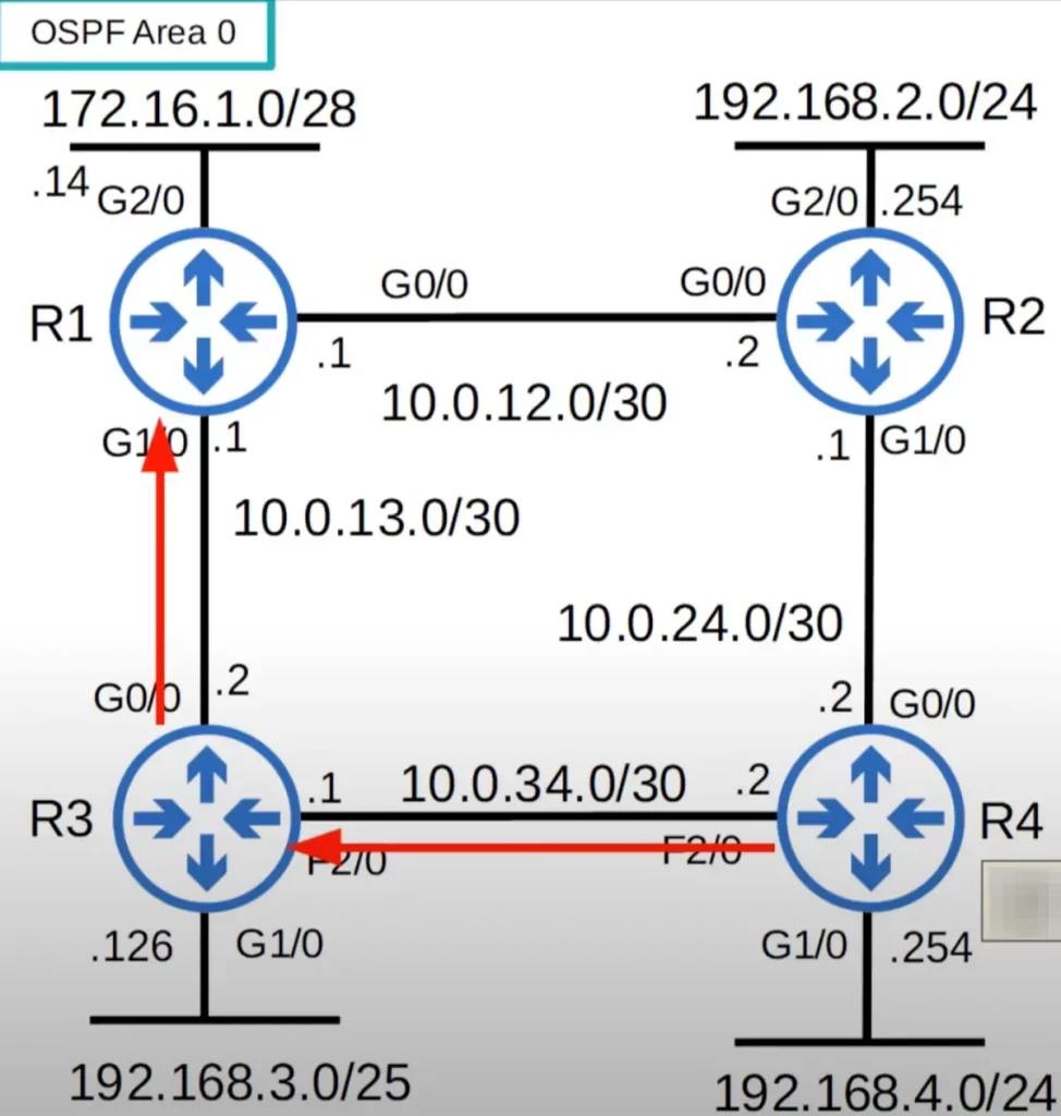
If R1’s G1/0 interface goes down for some reason, R4 will not be able to send the packet to R1.
If R1 has a loopback interface, 1.1.1.1, that is used to identify R1 instead of 10.0.13.1, then even if a physical interface fails (R1’s G1/0), when R4 receives a packet destined for R1’s loopback interface R4 will still be able to send the packet to R1.
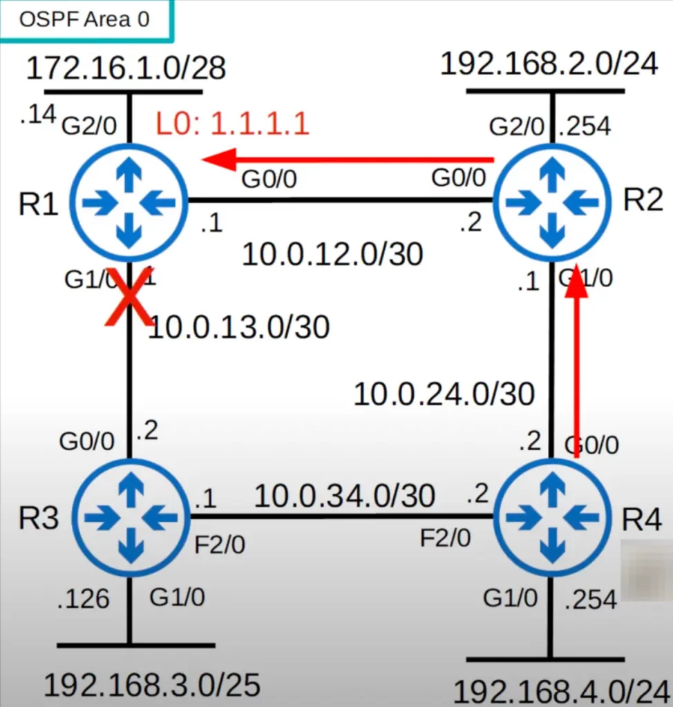
Configuring a loopback interface on a router provides an interface with an IP address that is always up and can consistently be used to identify and reach the router.
OSPF network types
Looking at the CCNA exam topics list, Section 3.0 IP Connectivity, subsection 3.4 says you must be able to “configure and verify single area OSPFv2”. Notice, 3.4b mentions the Point-to-point network type, and 3.4c mentions the Broadcast network type (DR/BDR selection). Those are the OSPF network types we will focus on in this lesson.
The OSPF network type refers to the type of connection between OSPF neighbors (routers).
There are three main OSPF network types.
1) Broadcast network type, which is enabled by default on Ethernet and FDDI interfaces. FDDI (Fiber Distributed Data Interfaces) is an old technology.
2) Point-to-point network type, which is enabled by default on PPP (Point-to-Point Protocol) and HDLC (High-Level Data Link Control) interfaces.
3) Non-broadcast network type, which is enabled by default on Frame Relay and X.25 interfaces.
OSPF broadcast network type
The OSPF connections we looked at previously used the broadcast network type, because they were all Ethernet connections. The default OSPF network type for Ethernet interfaces is broadcast.
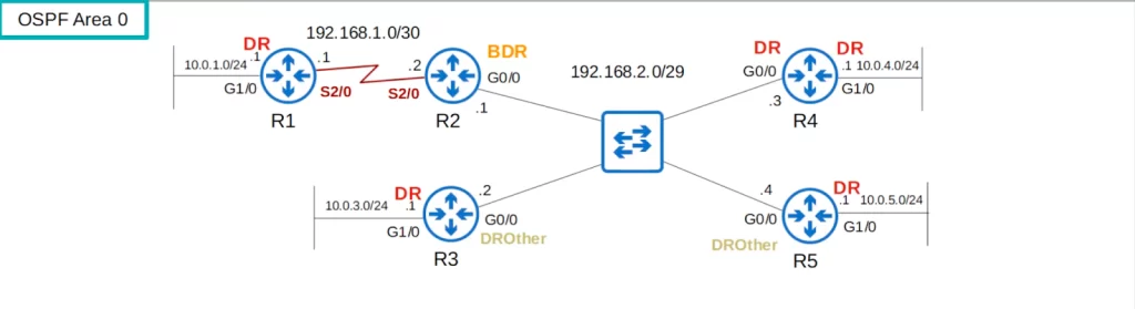
Ethernet is the most common type of physical connection in modern networks. In this network diagram, these are all Ethernet connections. “G” stands for Gigabit Ethernet. These connections between the routers are all using the broadcast network type.
Let’s cover a few characteristics of the broadcast network type.
*Routers dynamically discover neighbors by sending and listening for OSPF hello messages using the multicast address 224.0.0.5. Not all network types discover neighbors dynamically like this. With the non-broadcast network type you must manually configure neighbors on the router.
*The above diagram shows an example of a multi-access network, which is a network segment where multiple routers are connected. This is in contrast to point-to-point links, which only have two devices connected directly. Common examples of multi-access networks include Ethernet segments or hubs.
OSPF relies on exchanging routing information between routers. However, on multi-access networks, broadcasting all updates from each router can be inefficient and create unnecessary traffic.
*To address this, OSPF uses a concept called Designated Router (DR) and Backup Designated Router (BDR) election on each multi-access network.
- Designated Router (DR): This is the single router elected to be responsible for sending routing updates on the multi-access network. Only the DR is authorized to send updates about the entire network segment, reducing redundant broadcasts and improving efficiency. Other routers only send updates to the DR.
- Backup Designated Router (BDR): This acts as a backup in case the DR fails. If the DR goes down, the BDR takes over its responsibility.
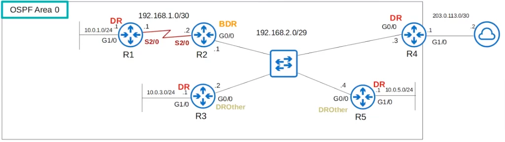
*A DR and a BDR must be elected on each subnet. In cases where there are no OSPF neighbors, like the G1/0 interfaces of R1, R3, R4, and R5, there is just a DR, no BDR.
*Routers which are not the DR or BDR for the subnet become a DROther (pronounced “D R other”).
Let’s look at the above network.
Each subnet needs a DR. In the subnets identified by DR in red there are no OSPF neighbors, so each router becomes the DR for the subnet.
Let’s say R2 is the DR in the 192.168.1.0/30 subnet between R1 and R2. R1 becomes the BDR for the segment. We will look at the DR/BDR election process shortly.
In the 192.168.2.0/29 subnet that R2, R3, R4, and R5 connect to, R5 might be the DR, for example, and R4 the BDR, and then R2 and R3 become DROthers.
Let’s see an explanation of how these elections work, and what is the purpose of the DR and BDR.
Broadcast – DR/BDR election
There is an order of priority that governs how the DR and BDR are elected.
*First, the router with the highest OSPF interface priority in the subnet becomes the DR for the segment.
However, all interfaces have the same priority by default, 1, so then the routers compare their OSPF router IDs.
*The router with the highest OSPF router ID becomes the DR for the subnet, and second place becomes the BDR.
*Since the default OSPF interface priority is 1 on all interfaces, by default, the router with the highest router ID becomes the DR for the segment.
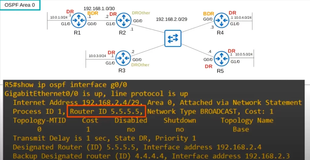
Looking at the above partial output from SHOW IP OSPF INTERFACE G0/0 on R5, notice the router ID. After configuring a loopback interface on each router, the IP address of the loopback interface became the router ID. If a router has loopback interfaces, the highest IP address on one of the loopback interfaces will be used as the router ID, unless the router ID was manually configured by an admin.
R5 has the highest router ID of the routers connected to the 192.168.2.0/29 subnet, so it became the DR.
Notice in the above CLI output R5’s “State DR”, and Priority, the default of 1. Also notice the DR (R5) and BDR (R4) for the segment are listed with their router IDs and the interface IP address in the subnet.
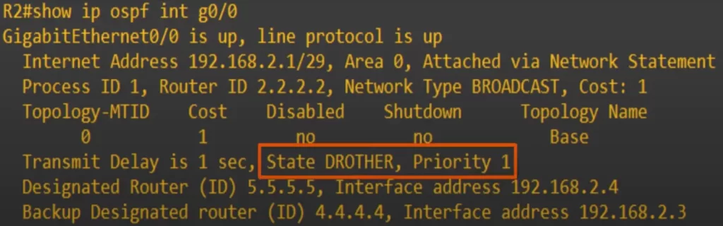
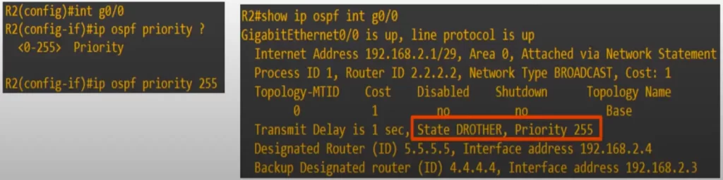
Here’s the same output for R2’s g0/0. Note R2’s state of DROTHER. What if we want to make R2 the DR for the segment instead of R5?
Broadcast – OSPF priority
The command to change the OSPF priority of an interface is IP OSPF PRIORITY, followed by the priority, with a range of 0 to 255.
Let’s change the OSPF priority of R2’s g0/0 interface to the maximum of 255. Now let’s check if R2 has become the DR for the segment.
R2’s state is still DROTHER, even though it has the highest priority. This is because the DR/BDR election is non-preemptive.
Non-preemptive means that once the DR/BDR are selected they will keep their role until OSPF is reset.
As a side note, if you set the OSPF interface priority to 0, the router would never become the DR/BDR for the subnet.
Let’s reset the OSPF process on R5. To restart OSPF neighbors, we used the clear ip ospf process command in privileged EXEC mode.
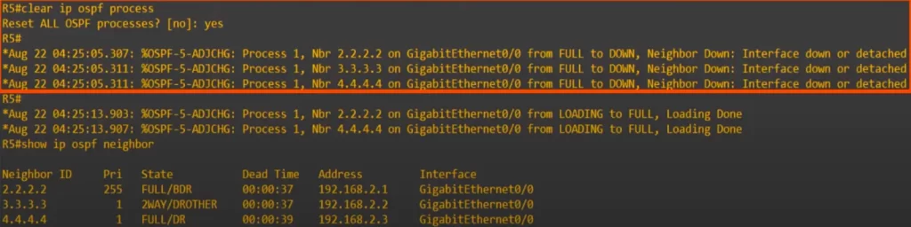
All of R5’s neighbors went DOWN.
Then R2 and R4 returned to the FULL state, but not R3. As you can see, R3 is listed as a DROther.
We then used the SHOW IP OSPF NEIGHBOR command to view the neighbor state of R5’s neighbors:
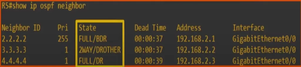
Let’s make sense of the CLI output.
*First, R4 became the DR, not R2. R2 became the BDR. When the DR goes down, the BDR becomes the new DR. R4, which was the BDR, instantly stepped up to be the new DR, and then an election was held between the other routers for the next BDR. R2 has the highest priority, 255, so it became the BDR.
*Next, R3 is a DROther, and is stable in the 2-way state. DROthers (R5 also became a DROther in this subnet) will only move to the FULL state with the DR and BDR of the subnet. The neighbor state with other DROthers will be 2-way.
Remember these two points. The BDR becomes the DR if the current DR is removed, even if the BDR does not have the highest priority. And DROthers do not form full adjacencies with other DROthers, they remain in the 2-way state.
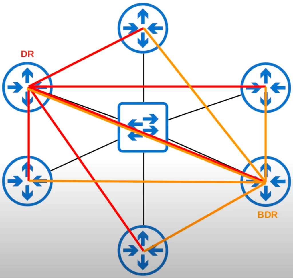
*In the broadcast network type, routers will only form a full OSPF adjacency with the DR and BDR of the segment.
*Therefore, routers only exchange LSAs with the DR and BDR. DROthers will not exchange LSAs with each other. Recall, in the 2-way state, routers have not shared LSAs with each other yet.
*All routers will still have the same LSDB, but this functionality of DR and BDR reduces the amount of LSAs flooding the network.
Think about it. If 6 routers are connected to the same segment and they all share LSAs with each other, we will end up with a whole lot of LSAs flooding and network congestion.
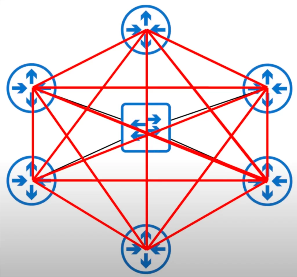
If routers only exchange LSAs with the DR and BDR, as you can see, the number of LSAs flooding around the network is reduced.
Note, when routers need to send messages to the DR and BDR they use multicast address 224.0.0.6. This is different from the OSPF all routers multicast address of 224.0.0.5.
Here’s a quick review of the OSPF neighbor process.
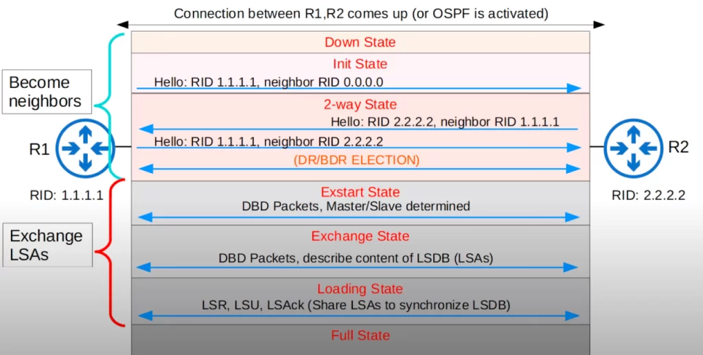
When routers become OSPF neighbors, connections between two DROthers stop at this point. Routers will only continue on to exchange LSAs and form a Full OSPF adjacency with the DR and BDR.
The DR forms a Full adjacency with all neighbors in the broadcast network segment. The DR does not form a neighbor relationship at all with itself.
To summarize, the DR and BDR form a Full adjacency with all routers in the subnet, including the DROthers. And DROthers will form a FULL adjacency only with the DR and BDR.
Let’s apply the SHOW IP OSPF INTERFACE BRIEF command to R3, which is a DROther. Notice the neighbor count on its G0/0 interface.
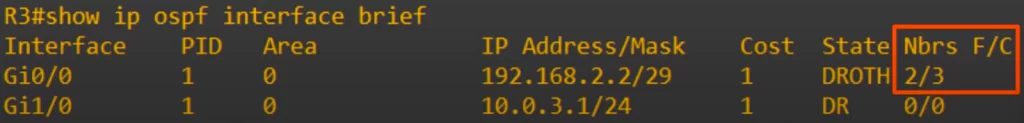
F indicates the number of full adjacencies, and C indicates the total count of neighbors. R3 has two Full adjacencies, with R2 and R4. But it has three total neighbors, R2, R4 and R5.
For more detail, here is SHOW IP OSPF INTERFACE G0/0 on R3.
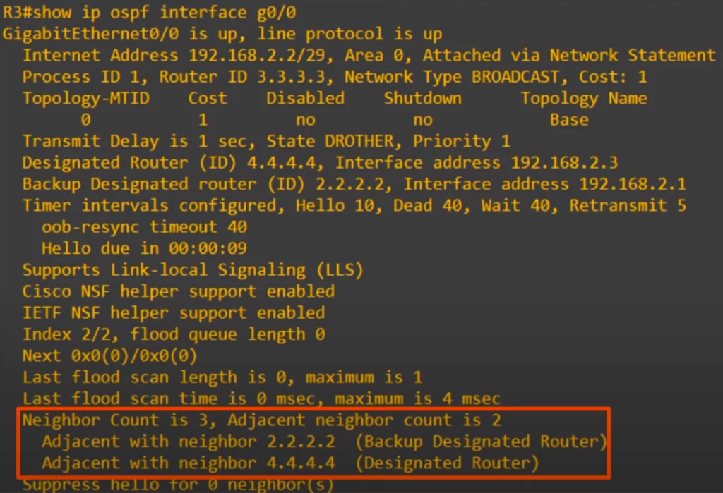
Neighbor Count is 3: that’s R3’s total number of OSPF neighbors. Adjacent neighbor count is 2: those are the neighbors R3 has formed a Full adjacency with. And below it, its two adjacent neighbors are listed. R2, the BDR, and R4, the DR.
Understand show ip ospf neighbor command output (cisco.com)
Understand show ip ospf interface command output (cisco.com)
OSPF point-to-point network type
An OSPF point-to-point network is a network that consists of two OSPF routers that are connected by a single point-to-point link.
Notice the connection between R1 and R2 was changed to a serial connection.
*OSPF point-to-point networks are enabled by default on serial interfaces that use PPP or HDLC encapsulations. PPP and HDLC are both Layer 2 encapsulations that are similar to Ethernet, but they are used on serial connections instead.
Serial interfaces are typically used for connecting routers together over a leased line or other high-speed serial connection.
PPP encapsulation provides error control and flow control for data transmissions over serial connections. HDLC encapsulation is similar to PPP encapsulation, but it is more efficient and can handle higher data rates.
*In an OSPF point-to-point network, there is no point in electing a DR and BDR. A DR and BDR are not elected. The two routers will form a Full adjacency with each other, without the need to elect a DR and BDR.
*As is the case in the broadcast network type, routers in point-to-point networks dynamically discover neighbors by sending/listening for OSPF hello messages using multicast address 224.0.0.5.
Here’s the output of SHOW IP OSPF NEIGHBOR on R2.
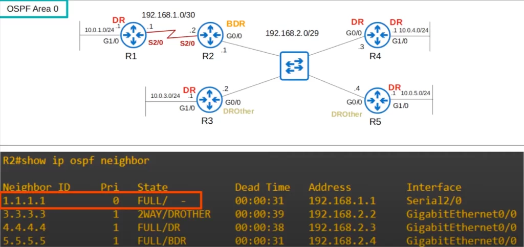
Notice that R2 has a full adjacency with R1. Instead of DR, BDR, or DROTHER, a dash is displayed. The point-to-point network type does not use DRs or BDRs.
Serial interfaces
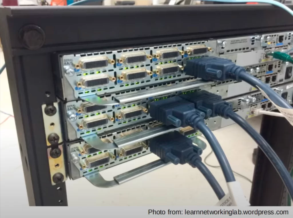
Serial connections are an old technology. They still exist, but Ethernet is much more dominant. Serial connections have been removed from the CCNA exam topics list except for the OSPF point-to-point network type.
This photo shows some serial interfaces and cables. Notice that both the ports and the cables are different from Ethernet cables.
To explain serial connections, let’s see how to configure R1’s S2/0 interface in the following simple topology consisting of two routers, R1 and R2.
One side (router) of a serial connection functions as DCE, Data Communications Equipment, and the other side functions as DTE, Data Terminal Equipment.
On serial connections, the DCE side needs to specify the clock rate, which is the speed, of the connection. In this case R1 has the DCE side of the cable and therefore R1 needs to tell R2 what speed the connection will operate at.
The command is clock rate. Using the question mark, you can see some standard values that can be used. All of these are in bits per second.
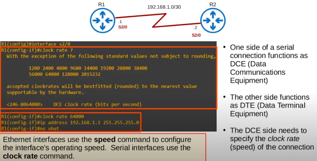
We configured a clock rate of 64000 bits per second (64 kilobits per second), added an IP address, and used NO SHUTDOWN to enable the interface.
Ethernet interfaces use the SPEED command to configure the interface’s operating speed. Serial interfaces use the CLOCK RATE command.
We check the interface with SHOW INTERFACE S2/0. Notice that the encapsulation is HDLC.
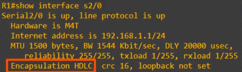
On Cisco routers, HDLC is the default encapsulation on a serial interface. Cisco’s own version is called cHDLC, and it displays as just HDLC in the CLI. This is a Layer 2 encapsulation, like Ethernet, except it’s used on serial connections.
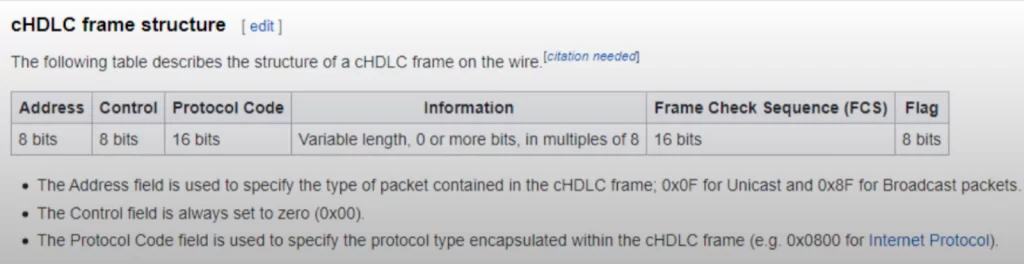
Here’s the structure of an HDLC frame, courtesy of Wikipedia. Note that there is no MAC address field in an HDLC frame.
Let’s see how to configure the router to use PPP encapsulation. We use the ENCAPSULATION PPP command on the interface. We enter do SHOW INTERFACE S2/0, and we see the encapsulation has changed to PPP. We did the same on R2, so the interface is up.
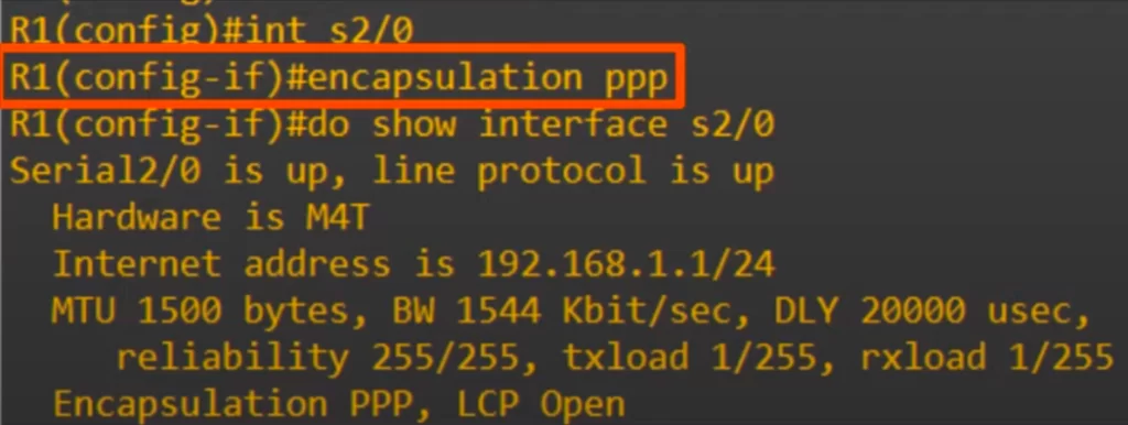
Note that if you change the encapsulation, it must match on both ends or the interface will go down.
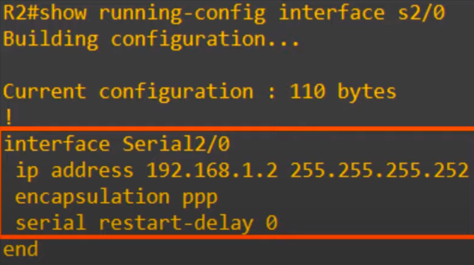
Here’s the configuration we did on R1.
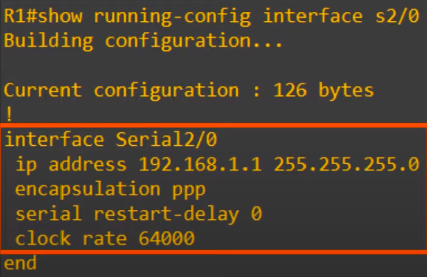
The SERIAL RESTART-DELAY 0 command was there by default. We only configured the IP address, encapsulation, and clock rate.
And here is the command on R2, without the CLOCK RATE command because it is the DTE end.
How can you tell which side is DCE and which is DTE? Use the command SHOW CONTROLLERS, followed by the interface ID.
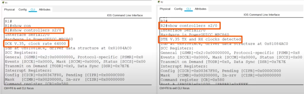
As you can see R1 is the DCE side of the serial connection, and it has the clock rate of 64,000 bits configured. Using the same command on R2, we can see that it is the DTE side, and that it has detected the Tx, transmit, and Rx, received clocks from R1.
Serial interfaces summary
Here’s a summary of what you should know about serial connection.
*The default encapsulation on serial interfaces is HDLC.
*You can configure serial interfaces to use PPP encapsulation instead with this command:
R1(config-if)#encapsulation ppp
If you change the encapsulation on one side, remember to change it on the other side too.
*One side of the connection is DCE and the other is DTE.
*You can identify which side is DCE and which is DTE with this command:
R1#show controllers interface-id
*Finally, remember to configure the clock rate, the speed of the connection, on the DCE side with this command:
R1(config-if)#clock rate bps
Configuring the OSPF network type
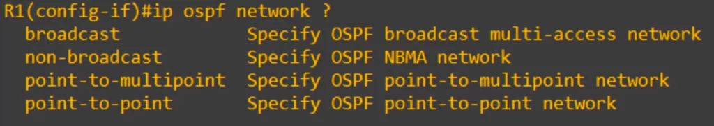
*To manually configure the network type of an interface, use the command IP OSPF NETWORK, followed by the network type.
*You may want to change the OSPF network type, for example, if two routers are directly connected with an Ethernet link, like in the diagram below, where a DR/BDR is not needed.
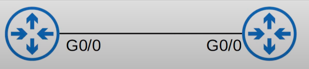
*Note: not all network types work on all link types. For example, a serial link cannot use the broadcast network type since serial links do not support Layer 2 broadcast frames, which is necessary for the broadcast network type.
Broadcast vs point-to-point chart
| Broadcast | Point-to-point |
| Default on Ethernet, FDDI interfaces | Default on HDLC, PPP (serial) interfaces |
| DR/BDR elected | No DR/BDR |
| Neighbors dynamically discovered | Neighbors dynamically discovered |
| Default timers: Hello 10, Dead 40 | Default timers: Hello 10, Dead 40 |
| Non-broadcast network type default timers = Hello 30, Dead 120 | |
OSPF neighbor/adjacency requirements
Usually, routers will become OSPF neighbors without issue, but let’s explore eight key requirements of OSPF neighbor relationships so that we can identify OSPF neighbor/adjacency problems if/when they occur.
1) The area number must match
2) Interfaces must be in the same subnet
3) OSPF process must not be shut down
4) OSPF router IDs must be unique
5) Hello and Dead timers must match
6) Authentication settings must match
7) IP MTU (maximum transmission unit) settings must match*
8) OSPF network type must match*
*Note, regarding the last two requirements, even if the settings do not match, the neighbors can become OSPF neighbors but OSPF will not operate properly.
Let’s do a run down of these eight OSPF neighborship requirements.
1) The area number must match for two routers to become OSPF neighbors. In other words, the routers must be in the same area.
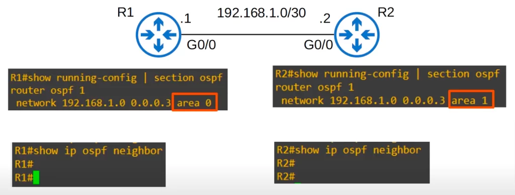
Consider the following topology of two routers.
Here is R1’s OSPF configuration. OSPF is enabled on R1’s G0/0 in area 0. OSPF is enabled on R2’s G0/0 is in area 1.
Running the SHOW IP OSPF NEIGHBOR command on both devices shows they have no OSPF neighbors.
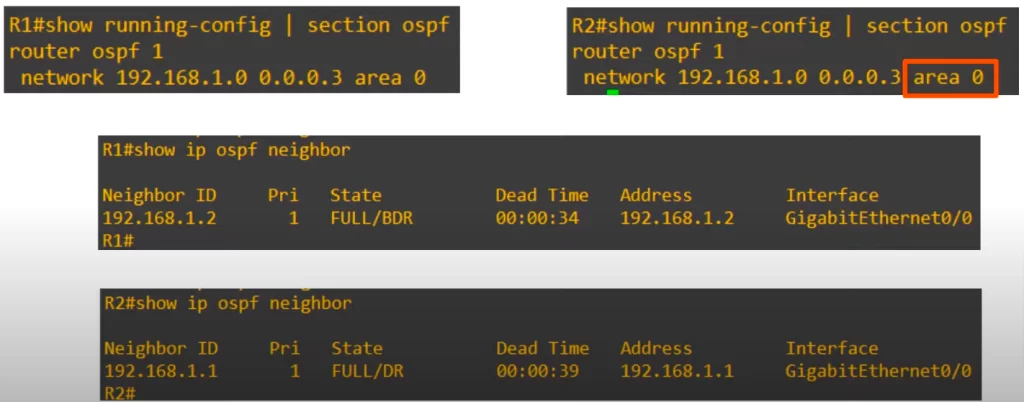
We can use the network command on R2 to change R2’s area to 0. As you can see, the routers then successfully became OSPF neighbors.
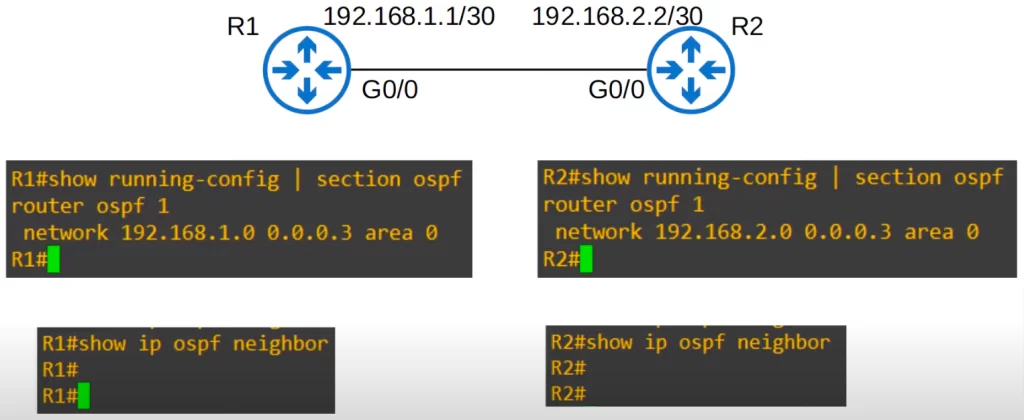
2) The interfaces must be in the same subnet for routers to become OSPF neighbors. To demonstrate with the following topology: R1’s and R2’s G0/0 interfaces are in different subnets. Let’s activate OSPF on both of the interfaces. But when we check for OSPF neighbors, they do not come up.
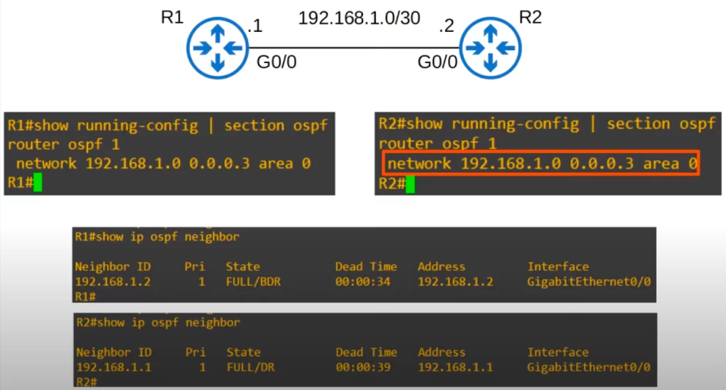
We configured R2’s interface in the same subnet as R1, and now R1 and R2 are OSPF neighbors again.
3) The OSPF process must not be shutdown. Manually shutting down the OSPF process on the router disables OSPF operation without removing the OSPF configurations.
To demonstrate, use the SHUTDOWN command from OSPF configuration mode on R2. A message is displayed indicating that R1’s state has changed from FULL to DOWN. Notice, there are no neighbors displayed in SHOW IP OSPF NEIGHBOR.
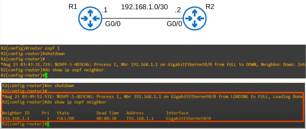
Then we enabled OSPF again with NO SHUTDOWN. We have a message indicating that the neighbor R1 is back up, and R1 shows up in SHOW IP OSPF NEIGHBOR.
4) The OSPF router IDs must be unique.
Recall, the priority order for selecting a router ID is: 1) it is manually configured, 2) it is the highest loopback interface, and 3) it is the highest active IPv4 address of any of a router’s physical interfaces.
In the following topology, we have not configured the router IDs of R1 and R2, and we also have not configured any loopback interfaces, so each router has selected its G0/0 IP address as its router ID, 192.168.1.1 for R1 and 192.168.1.2 for R2.
So we configured 192.168.1.1 as the router ID for both R2 and R1. We have to reset the router or use CLEAR IP OSPF PROCESS for the new router ID to take effect. We used CLEAR IP OSPF PROCESS on R2.
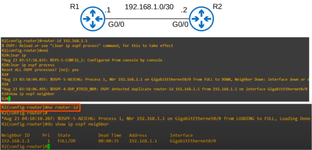
Immediately the neighbor goes down because we cleared the OSPF process. But then instead of the neighbor coming back up, the following message is displayed: “OSPF detected duplicate router-id 192.168.1.1 from 192.168.1.1 on interface GigabitEthernet0/0”.
We can fix this by using the NO ROUTER-ID command to remove the manually configured router ID.
R2’s router ID returns to 192.168.1.2 and the neighbor comes up again.
We did not have to reset the OSPF process again because R2 had no other OSPF neighbors and changing R2’s router ID would not affect other neighbors.
5) The hello and Dead timers must match. In both broadcast and point-to-point network types, the defaults are 10 seconds and 40 seconds. But these settings can be changed manually. The hello and Dead timers are configured directly on the interface.
Here’s how to configure the hello timer. IP OSPF HELLO-INTERVAL, followed by the interval in seconds. We set it to 5 on R2. Then the Dead timer. IP OSPF DEAD-INTERVAL. We set it to 20 on R2.
As you can see, the neighbor went down. Even if we had only changed one of them, the hello timer or the Dead timer, the neighbor would still have gone down.
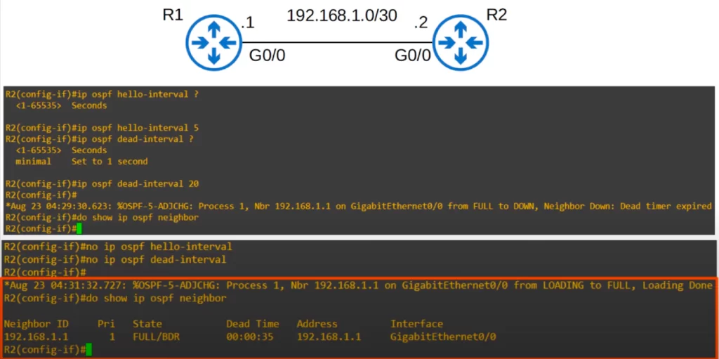
To return the timers to their default values, use NO IP OSPF HELLO-INTERVAL and NO IP OSPF DEAD-INTERVAL. Now that the hello and Dead timers match again, the neighbor is back up.
6) Authentication settings must match.
If we configured an OSPF password, then the router will only become neighbors with routers that have a matching OSPF password.
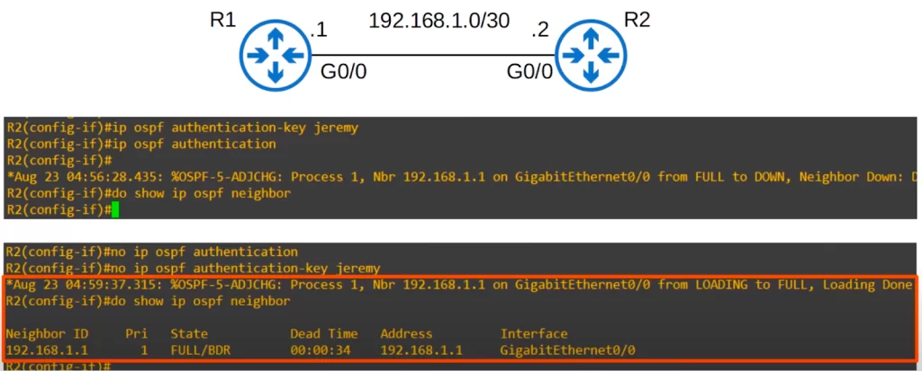
The OSPF password is configured directly on the interface. To configure the password, we used IP OSPF AUTHENTICATION-KEY, followed by a password, jeremy.
We still need to enable OSPF authentication on the interface. We used the command IP OSPF AUTHENTICATION to enable the authentication.
The neighbor went down because R1 is not providing R2 a matching password. R1 is not providing R2 with any OSPF password, because we have not configured OSPF authentication on R1.
To bring the neighbor back up, we removed the authentication from R2. Alternatively, we can configure the same authentication settings on R1.
7) The IP MTU settings on the interfaces must match.
The IP MTU is the maximum transmission unit for IP packets. It is the largest size packet that can be sent out of the interface without fragmentation. The default IP MTU is 1500 bytes, but it can be configured to a different value. You can configure the IP MTU of an interface with this command IP MTU, followed by the MTU in bytes.
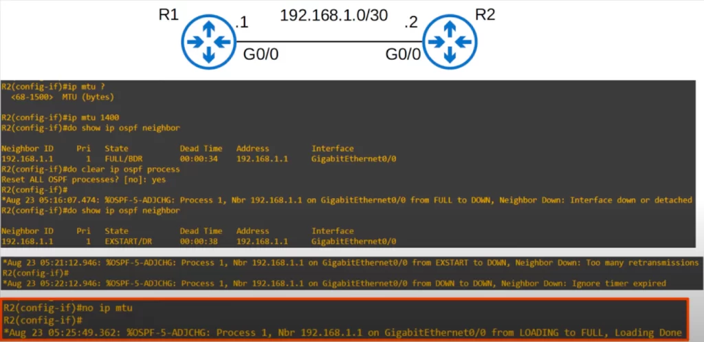
We changed the IP MTU on R2’s G0/0 to 1400. R1’s and R2’s IP MTU no longer match. R1 has the default 1500 on its G0/0. We then checked the neighbor table. R1 and R2 remained neighbors.
Then we reset the OSPF process on R2. We waited a minute without seeing a message indicating that the neighbors had reached the Full state. We checked the neighbor table again and found it stuck in the EXSTART state. After waiting a few minutes, a few more messages were repeatedly displayed. So OSPF is not functioning properly.
We used NO IP MTU to return the MTU to the default value, and then R1 and R2 reached the FULL state.
If your OSPF neighbors are having trouble reaching the FULL state make sure to check the MTU settings.
8) The OSPF network type must match.
What happens if they don’t?
We configured a loopback interface on R2 with an IP address 2.2.2.2, and advertised it to R1. Then we changed the network type on R2’s G0/0 to point-to-point. R1’s G0/0 is using the default broadcast network type.
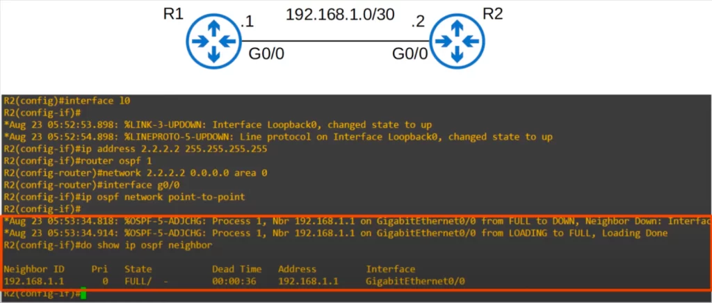
A message is displayed saying the neighbor went down, but then it went back to the FULL state. And R1 displays as FULL in SHOW IP OSPF NEIGHBOR.
Let’s check R1. R2 appears in the neighbor table in the FULL state, so you might think OSPF is working fine. But look at the routing table. R2’s loopback address should be in R1’s routing table, but it’s not.
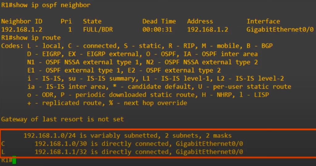
It can be tricky to troubleshoot OSPF adjacency problems when the OSPF network type does not match. The neighbor state can be Full, and it would seem like everything is working fine, but the routers do not form an adjacency.
Troubleshoot OSPF neighbor problems (cisco.com)
OSPF LSA types
LSAs are not explicitly stated in the CCNA exam topics list, but you should still be aware of what they are and there is a good chance you will encounter them in your networking career.
This section sheds light on the three most basic LSA types: Type 1 (Router LSA), Type 2 (Network LSA), and Type 5 (AS external LSA).
To do so, we have modified an earlier topology, adding an Internet link on R4. R4 has a default route to the Internet, and we use the DEFAULT-INFORMATION ORIGINATE command to make R4 advertise the default route into OSPF to other routers.
*All routers in the same OSPF area share the same LSDB. The OSPF LSDB is made up of LSAs.
*There are 11 types of LSA, but we are focusing on the three most basic LSA types. Those are Type 1 (Router LSA), Type 2 (Network LSA), and Type 5 (AS external LSA). Let’s take a brief look at each type.
1) Type 1, Router LSA
- Every router running OSPF generates this type of LSA.
- The router LSA identifies the router using its router ID. When a router receives a router LSA, it uses the router ID to identify the router that originated the message. This information is then used to build up the router’s routing table.
- The router LSA lists networks attached to the router’s OSPF-activated interfaces.
2) Type 2, Network LSA
- Generated by the DR of each multi-access network. An example of a multi-access network is an Ethernet network using the broadcast network type.
- Lists the routers which are attached to the multi-access network. The DR floods the multi-access network with the network LSA message containing the summarized information about all attached networks. This way, all routers on the segment receive the latest routing information efficiently.
3) Type 5, AS external LSA
- Generated by ASBRs to describe routes to destinations outside of the AS (OSPF domain)
Here’s a look at the LSDB on R1, using the command SHOW IP OSPF DATABASE.
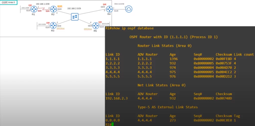
Because all routers in the area have the same LSDB, the output for all routers will be the same no matter which router we use the command on.
Notice, each router has generated a Type 1 Router LSA identifying itself. The contents of each LSA is not shown in this view, but each of these router LSAs contains information about the networks each router is connected to.
Notice, there is only one Type 2 Network LSA, generated by R4 for the 192.168.2.0/29 subnet. No Type 2 LSA is generated in the cases of R1, R3, and R5 even though these three routers are DRs on their G1/0 interfaces. This is because no other routers are connected to the interfaces.
Finally, notice that R4 has generated a Type 5 AS-External LSA. R4 is using this LSA type to share its default route to the Internet with the other routers.
Command review
R#show ip ospf interface interface
→to check area, process ID, router ID, network type, ospf cost, ospf neighbor state, interface priority, DR ID, and BDR ID
R#show ip ospf interface brief
→to check the ospf cost and neighbor status
R(config-if)#ip ospf priority priority
→to change the OSPF priority of an interface (0-255)
R#clear ip ospf process
→to reset the OSPF process on a router/to restart OSPF neighbors
R#show ip ospf neighbor
→to check adjacencies; neighbor ID, priority, adjacency state (FULL/DR, 2way/DROTHER, etc.), Dead time, and neighbor address and interface
R(config-if)#ip ospf network network-type
→to manually configure the network type of an interface
>Serial interface configurations example:
R1#show interface s2/0
R1(config)#interface s2/0
R1(config-if)#clock rate 64000
→i.e., 64000 bits per second
R1(config-if)#encapsulation ppp
→to configure the router to use PPP encapsulation (HDLC is the default encapsulation on a serial interface)
R1#show running-config interface s2/0
→to check encapsulation, and to check clock rate on DCE router
R#show controllers interface-id
→to identify which side is DCE and which is DTE
>OSPF neighbor/adjacency requirements:
R#show running-config | [section ospf]
R(config-if)#ip ospf hello-interval seconds
→to configure the ospf hello timer. To return the timer to its default value use NO IP OSPF HELLO-INTERVAL
R(config-if)#ip ospf dead-interval seconds
→to configure the ospf dead timer. To return the timer to its default value use NO IP OSPF DEAD-INTERVAL
R(config-if)#ip ospf authentication-key password
R(config-if)#ip ospf authentication
→to configure an OSPF password. Add NO to remove the authentication
R(config-if)#ip mtu mtu-bytes
→to configure an IP MTU value (the default IP MTU is 1500 bytes). Add NO to return the MTU to the default value
R#show ip ospf database
→to check the LSDB on a router
Free CCNA | Configuring OSPF (3) | Day 28 Lab – Notes
Key learnings
*Why configure a loopback interface on a router?
*The DR/BDR election process.
*OSPF interface priority configuration.
*OSPF network types broadcast and point-to-point.
*Point-to-point – clock rate configuration, and PPP encapsulation configuration.
*How to manually configure the OSPF network type.
*OSPF neighbor/adjacency requirements (troubleshooting OSPF adjacency problems).
*The three most basic OSPF LSA types: LSAs Type 1 (Router LSA), Type 2 (Network LSA), and Type 5 (AS external LSA) – roles in OSPF adjacency/IP connectivity within OSPF areas.
Practice quiz questions
Quiz question 1
Which option states a characteristic of the OSPF point-to-point network type that is different than the OSPF broadcast network type?
A. DR/BDR elections are held.
B. DR/BDR elections are not held.
C. Neighbors are dynamically discovered.
D. Neighbors are not dynamically discovered.
The answer is B. In the OSPF point-to-point network type, DR and BDR elections are not held. C. Neighbors are dynamically discovered is a correct statement about the point-to-point network type, but it is also true about the broadcast network type.
You can find four more practice questions for this lesson (plus a bonus one) in Jeremy’s video lesson OSPF Part 3, cited below.
Key references
Note: The resources cited below (in the “Key references” section of this document) are the main source of knowledge for these study notes/this lesson, unless stated otherwise.
Free CCNA | OSPF Part 3 | Day 28 | CCNA 200-301 Complete Course
Free CCNA | Configuring OSPF (3) | Day 28 Lab | CCNA 200-301 Complete Course
Other references/resources
OSPF Network Types – FINALLY, an explanation that makes sense – Practical OSPF
Related content
Compliance frameworks and industry standards
How data flow through the Internet
How routers become OSPF neighbors
How to break into information security
IT career paths – everything you need to know
Job roles in IT and cybersecurity
Network security risk mitigation best practices
The GRC approach to managing cybersecurity
The penetration testing process
The Security Operations Center (SOC) career path
Back to DTI Courses


