This post explains what happens when you type www.google.com into a web browser. It constitutes Lesson 7 of the module How data flow through the Internet. After completing this lesson you will be able to apply everything you learned in this module to answer the very common Network Engineering interview question, what happens when you type www.google.com into a web browser?
- Learning objectives
- Introduction
- Phase 1: host A (client/web browser) to host B (DNS server)
- Phase 2: host B (DNS server) responds to host A (client/web browser)
- Phase 3: host A sends an HTTP request to the web server
- Key lesson takeaways
- Key references
You may also be interested in How data flow through the Internet.
Learning objectives
- Explain the steps involved in transmitting a packet from one endpoint to another across the Internet
- Understand how the MAC address, ARP, and routing tables facilitate data flow through a network
Introduction
This is the final lesson of the module How data flow through the Internet. The purpose of this module is to teach you the very core of networking – how data flow through a network.
In this module we talked through the OSI model and the different functions each layer is responsible for. We talked through how hosts on the same network communicate with each other regardless of how they are connected. We also talked through how hosts on foreign networks speak with each other whether they are connected behind one router or multiple routers or on opposite sides of the Internet. We talked through switches and how they facilitate communication within a network. We discussed what routers do and how they learn routes and hand data off to one another.
In this lesson we’re going to tie elements from each of those lessons together into a comprehensive summary lesson.
Understanding how data flow through a network fundamentally comes down to understanding three tables: the MAC address table, the ARP table, and the routing table. The MAC address table is a mapping of a switch port to a MAC address. The ARP table is a mapping of an IP address to a MAC address. And the routing table is a mapping of an IP network to the next hop IP address.
In this lesson we will go over everything that happens with these three tables as data flow through the network topology depicted in Figure 1. We’re going to follow step by step a packet traveling from host A to host B and back, and a packet traveling from host A to host C and back to see in action how these three tables are used to facilitate that process of data flow. In doing so, we are explaining what happens when someone types www.google.com into a web browser.
Browsing to a website essentially involves two phases. First, using DNS to resolve a domain name into an IP address. Second, sending an HTTP request to that IP address.
When you type a website into a browser it will first make a request to a DNS server asking for the IP address of the website you just typed into the browser. Then the DNS server will provide an IP address and this will allow host A to make a request to the web server IP address.
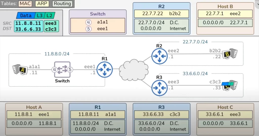
In our illustration (Figures 1 and 2) the first thing we do is send a DNS request (a packet) from host A (a browser/a client) to host B (a DNS server). The DNS server (host B) will then respond with the IP address of the web server for the domain we are trying to visit (www.google.com). Host A (our browser) will then send an HTTP GET request (a packet) to that web server IP address for www.google.com (host C).
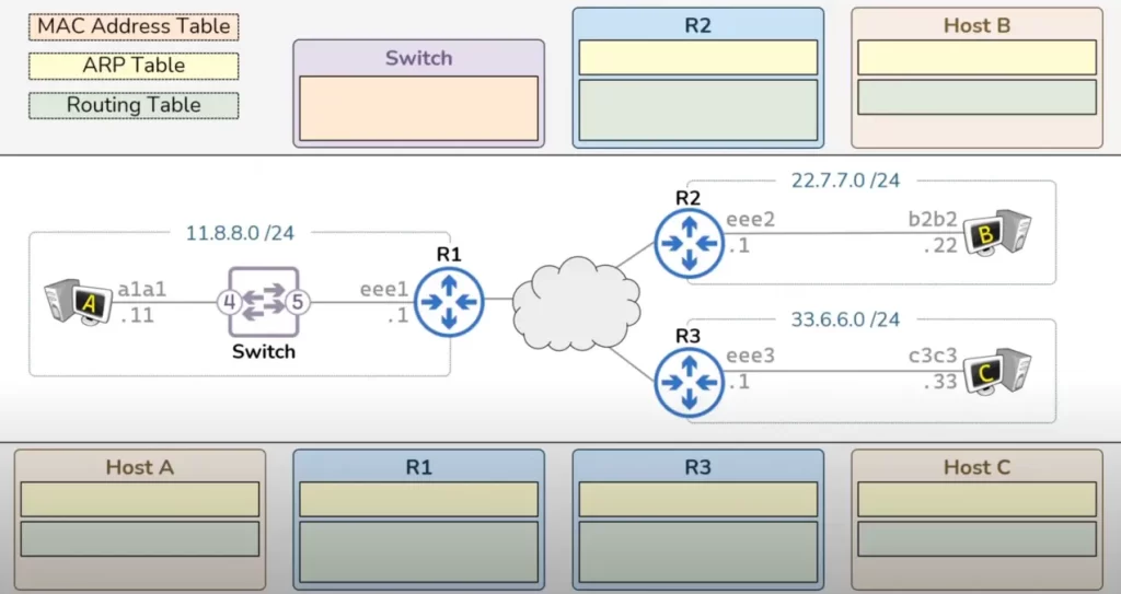
This topology has three routers (R1, R2, and R3) and three hosts (A, B, and C). Each host exists within a network and all the devices have IP addresses in their respective network.
Remember, all these devices – hosts, switches, and routers – follow consistent packet processing rules. If you understand those rules you can scale this topology to hundreds of devices and still walk your way through each step necessary.
To keep things simple, the illustration only shows the first four digits of MAC addresses. Since we are only sending traffic through the switch and not to or from the switch, the switch’s MAC address and IP address are irrelevant. So for our switch we only need a label for the two switch ports – i.e., port 4 and port 5.
Each of the devices in the Figure 1 topology is going to use one or more of the tables shown to process data. The switch is only going to have a MAC address table. The routers have both an ARP table and a routing table. Hosts also have both an ARP table and a routing table.
Both the MAC address table and the ARP tables are going to be populated dynamically as traffic flows through the network. The routing table however must be populated in advance. Recall from Lesson 5, if a router receives a packet with a destination IP address not in its routing table that packet will be dropped.
Let’s fill in all the entries for all the routing tables in the Figure 1 topology starting with host A’s routing table.
Host A only needs a default gateway (default route). The default route will be represented as a route for the 0.0.0.0 /0 network which includes all IPv4 addresses. This route points to the IP address of R1’s interface in the 11.8.8.0 network, i.e., to 11.8.8.1. This will tell host A to use R1 anytime it is trying to speak to anything on a foreign network.
Host B will also have a default gateway pointing to the interface IP address on R2 22.7.7.1. And host C will have a default gateway pointing to this interface IP address on R3 33.6.6.1.
Each router will have two routes. First, each router will have a directly connected route for the network that they are attached to: R1 has a directly connected route for the 11.8.8.0 /24 network. R2 has a directly connected route for the 22.7.7.0 /24 network. R3 has a directly connected route for the 33.6.6.0 /24 network. Second, each router will have a default route pointing to the Internet.
Normally that default route would point to a specific router IP address somewhere on the Internet, but to keep things simple we will simply abstract that away.
Phase 1: host A (client/web browser) to host B (DNS server)
Now we are ready for host A to send some data to host B.
Host A will start by adding a L3 header to its data to facilitate the end to end delivery of a packet. The source IP address of this packet will be the IP address of host A (11.8.8.11) and the destination IP address of this packet will be the IP address of host B (22.7.7.22).
The first thing host A will do is compare the destination IP address of the packet with its own IP address and subnet mask to determine that the destination IP address is on a foreign network. Therefore this packet must be sent to host A’s default gateway which is R1.
Initially, host A’s ARP table will be empty, and host A would not know R1’s MAC address and is therefore unable to construct the necessary L2 header which will take the packet across the first hop, to R1’s NIC (eee1).
So host A will first go through the ARP process to resolve R1’s MAC address. The ARP request will have a L2 header with a source MAC address of host A and a destination MAC address of all f’s – that’s the broadcast MAC address. This will tell the network that this ARP request should be sent to everybody in this network.
When host A puts the data on the wire it will arrive on the switch. Anytime something is received on a switch, the switch will try to learn the mapping between the receiving switch port and the source MAC address. In this case the source MAC address of this frame is a1a1 and the receiving switch port is port 4. Therefore our switch is going to learn that something out port 4 owns the MAC address a1a1.
Then the switch will look at the destination MAC address. It is all f’s which tells the switch it should do the flooding action to send the frame out all ports. That frame will be sent out port 5 where it will arrive on R1. Upon arriving to R1, R1 will get to learn the ARP mapping of the sender.
By receiving the ARP request R1 is able to learn that a device with the IP address 11.8.8.11 maps to the MAC address a1a1. Then R1 will generate an ARP response. This ARP response is going to have a source MAC address of R1’s NIC and a destination MAC address of host A. This is a unicast ARP response meant to be delivered directly back to host A.
R1 will put that on the wire where it will arrive on the switch. The switch will learn that a device out port 5 owns the MAC address eee1. Then the switch will look at the destination MAC address a1a1. The switch already knows that this MAC address exists out port 4 and will therefore forward this frame out port 4 where it will finally arrive back to host A.
When host A receives the frame it will learn the MAC address that it was trying to resolve, i.e., that the IP address 11.8.8.1 maps to the MAC address eee1. Now host A has the necessary information to complete a L2 header which will take the data packet to the router, i.e., to the next hop. That L2 header will have a source MAC address of host A and a destination MAC address of the router.
Host A will put the data on the wire where it will arrive on the switch. The switch will look at the destination MAC address to determine that the frame should be forwarded out port 5 towards R1.
When the frame arrives to R1, R1 will strip the L2 header which has served its purpose. Then R1 will look at its routing table to determine where it’s going to send this packet next. The destination IP address of this packet is 22.7.7.22 which matches R1’s default route (0.0.0.0 /0 Internet) – meaning, R1 knows that this packet will be sent across the Internet. Normally R1’s default route would point to a specific router on the Internet but for convenience we have abstracted this process out.
The packet will be passed from router to router across the Internet until it finally gets to R2. When it arrives to R2, R2 will look at its routing table to try and figure out how to deliver this packet. R2 will see that the destination IP address points to a directly connected route (22.7.7.0 /24) and R2 will know it will deliver the packet to its final hop within the directly connected network that R2 is attached to.
But because R2’s ARP table is still empty, R2 cannot add the L2 header necessary to take the packet to host B. R2 needs to send an ARP request to resolve the IP address of host B to its (host B’s) MAC address. The ARP request will be sent as a broadcast with R2’s source MAC address.
Upon receiving the ARP request host B will learn the ARP mapping of the sender of that ARP request, i.e., host B will learn that the IP address 22.7.7.1 maps to the MAC address eee2.
Host B will then generate a response. That ARP response will be a unicast frame sent with a source MAC address of b2b2 and a destination MAC address of eee2. That ARP response will be put onto the wire where it will arrive on R2. R2 will learn the ARP mapping that it was trying to resolve, that the IP address 22.7.7.22 maps to the MAC address b2b2.
Now R2 has all the information necessary to add the L2 header that will take the packet to host B. That L2 header is going to have a source MAC address of R2 and a destination MAC address of host B. R2 can now put the packet on the wire where it will finally arrive on host B.
Note: normally, a host would not be directly connected to a router. Normally a host would be connected to a switch which would then possibly be connected to other switches which would then finally connect to the router.
Once the packet arrives on host B, host B will discard the L2 header which has served its purpose. Host B will then discard the L3 header which has served its purpose. And now host B can finally process the data payload. Once host B has processed the data it will generate a response, also a data payload which includes a bunch of 1’s and 0’s.
Phase 2: host B (DNS server) responds to host A (client/web browser)
Now we will go through all the steps required to get this data payload back through the network from host B to host A. This phase will go much quicker than before because most of our tables have already been populated.
Host B will start by adding a L3 header onto that data with a source IP address of host B and a destination IP address of host A. Since this packet is going to something on a foreign network it must be sent to R2’s IP address, and at this point host B already has the ARP mapping for R2’s IP address and can therefore put together the L2 header necessary to get this packet across its first hop.
Upon arriving on R2, R2 will strip the L2 header and then R2 will look at its routing table to figure out where this package should go next. In this case the destination IP address 11.8.8.11 only matches the default route so R2 knows that this will be sent out towards the Internet. And again, we’ve abstracted that process out for the sake of simplifying the illustration. The packet will be handed from router to router across the Internet where it will finally arrive on R1.
Upon arriving on R1, R1 will look at its routing table and determine that the destination IP address matches the directly connected route, so R1 knows that this destination IP address is the final hop for this packet. R1 also knows the MAC address for that particular IP address so R1 has all the necessary information to construct a L2 header that will take the packet across its final hop. That L2 header will have a source MAC address of R1 and a destination MAC address of host A. R1 can then put that packet onto the wire where it will arrive on the switch.
The switch will to try to learn – it will try to map the receiving switch port, port 5, to the source MAC address of the incoming frame eee1, and the switch will find that it already has that entry in its MAC address table for this mapping. The switch will then look at the destination MAC address a1a1 and the switch will know it has to forward the frame out port 4.
The packet will finally arrive on host A. Host A will strip the L2 header and the L3 header and finally host A will process that response data.
Thus, we went over everything that happens to get data from host A all the way to host B and back again to host A. We explained how each of the devices involved in this process used a MAC address table, an ARP table, and a routing table to make this happen.
Phase 3: host A sends an HTTP request to the web server
Next, host A (our browser) will send some data (an HTTP GET request) to host C.
The first step that host A will take to send data to host C – as you must have guessed by now – will be to construct a L3 header with the source IP address of host A and a destination IP address of host C.
Since host A knows its packet is heading to a foreign network, host A will look at its default route to determine the default gateway’s IP address which is R1. And since host A already has the ARP mapping for its default gateway’s IP address it can already put together the L2 header which will take this packet to R1. The L2 header will have a source MAC address of host A and a destination MAC address of R1. Host A will put the data on the wire where it will arrive on the switch.
The switch will look at the destination MAC address to determine where to send the data. Since the MAC address exists out port 5, the switch will forward the frame out port 5.
The data will then arrive on R1 and R1 will discard the L2 header and will look at its routing table to determine where to send the packet next. The destination IP address on this packet matches the default route so R1 will send the packet across the Internet where it will finally arrive on R3.
Upon receiving the packet, R3 will look at the destination IP address and determine that it matches the directly connected route in R3’s routing table. This tells R3 that it’s going to have to put a L2 header onto this packet that matches the MAC address associated with the IP address 33.6.6.33.
But R3 cannot construct the appropriate L2 yet because R3 does not have anything in its ARP table. So – again, as you must have guessed already – R3 will send out an ARP request to the broadcast MAC address which will ensure that this ARP request gets delivered to everybody on the network 33.6.6.0 /24.
Upon receiving the ARP request host C will learn the ARP mapping of the sender of that ARP request, i.e., the IP address 33.6.6.1 and the MAC address eee3. Then host C will put together the ARP response with a L2 header with a source MAC address of host C and a destination MAC address of R3.
R3 will learn the ARP mapping it needed, and now R3 has everything it needs to put together the appropriate L2 header which will take the packet across its final hop to host C. R3 will put the packet onto the wire where it will arrive on host C. Host C will discard the L2 header. And the L3 header. And will finally process the data.
Now host C will respond back to host A
And you know the drill by now!
Host C will throw a L3 header onto that packet with a source IP address of host C and a destination IP address of host A. Host C knows it’s trying to speak to something on a foreign network so host C knows that the packet must be sent to the default gateway, R3. And host C already has the ARP mapping for the default gateway so it has all the information it needs to put together the L2 header which includes the destination MAC address of R3. Host C will put that packet onto the wire where it will arrive on R3.
R3 will strip the L2 header and then R3 will look at its routing table to determine where to send this packet. The destination IP address of this packet matches the default route so R3 will send that packet out towards the Internet where it will finally arrive on R1.
R1 will look at its routing table and compare the destination IP address to see which route it should send the packet to. In this case this destination IP address matches a directly connected route which means R1 knows that this packet will be delivered to its final hop. R1 already knows the ARP mapping for this particular destination IP address. So R1 has all the necessary information to construct a L2 header, with a source MAC address of R1 and a destination MAC address of host A. The packet will be sent onto the wire and arrive on the switch.
The switch will look at the destination MAC address to determine that this frame should be sent out port 4. The switch will put the frame onto the wire, arriving finally on host A. Host A will then strip the L2 header. Strip the L3 header. And finally host A will process the response from host C.
And Bob is your uncle.
Key lesson takeaways
- Network devices follow consistent packet processing rules
- MAC address table, ARP table, routing table
Key references
How Data moves through the Internet – Networking Fundamentals (PracNet)
Related content
Compliance frameworks and industry standards
How to break into information security
IT career paths – everything you need to know
Job roles in IT and cybersecurity
Network security risk mitigation best practices
The GRC approach to managing cybersecurity
The penetration testing process
The Security Operations Center (SOC) career path
Back to DTI Courses


